![[Translate to Englisch:] gebaeudeanalyse-algorithmen](/fileadmin/_processed_/a/6/csm_Hero-nextGen_ee38e865f1.png)
To understand this, you need to know that we are currently working with two algorithms - one that analyzes AutoCAD Architecture models and one especially for Revit models. Both are actively maintained and developed, with the algorithm for Revit being the newer, more modern one that is simply capable of more. For example, this makes it possible to analyze IFC architectures in linked models, which enables an advantageous separation of responsibilities in BIM processes. This option is also increasingly requested by our AutoCAD customers as a substitute for converting IFC to AutoCAD Architecture models. Since the better is the enemy of the good and there is rarely anything that cannot be improved upon, we decided to develop a new algorithm that will replace the two existing ones and will allow us to cover all required scenarios. We would like to share with you in this article the thoughts we had about it, what it changes and what it improves.
IFC-LINK VS. NATIVE ARCHITECTURE MODELLING
You have probably heard in many presentations on open BIM and IFC that IFC is a transport format for building models that can perform a wide variety of tasks, except for one: Transferring models from one authoring system to another without loss. This is comparable to a PDF document. It is perfect for holding content, but not for cleanly transferring a Microsoft Word document to LaTeX or Adobe Illustrator.
Now, if you try to create a native Revit or AutoCAD architecture model from an architecture application, such as ArchiCAD, via IFC, this is only feasible to a very limited extent due to the different modeling options.
In the past, we have chosen this way against better knowledge to be able to analyze IFC models also under AutoCAD. We generated "true" AutoCAD Architecture walls, windows, and doors from IFC walls, windows, and doors. The accuracy of the representation was given only second priority; after all, the primary goal was to determine building loads. Another reason for this approach was the prevailing relatively good quality of the IFC files existing in the field. After the import, some of the models had such large deficits that they had to be corrected manually - and that is only possible if you generate a "true" or native model by import.
From today's perspective, these arguments do not satisfy the requirements for agility and commitment of collaborative planning processes. The expert MEP planner cannot and does not want to deal with the adjustment of incorrectly modeled/exported buildings, especially since, depending on the BIM process, frequent reconciliation of models is required, which would lead to frequent correction processes. Another sticking point here is the reversal of responsibilities. By modifying the model, the expert MEP planner takes on a task in an area where really only the architect should have authority. Moreover, he can never return results of his work into the BIM process. They are therefore lost. Last but not least, conversion to native models always involves an additional step of interpretation. The geometric correctness of the components may well be lost in favor of their editability.
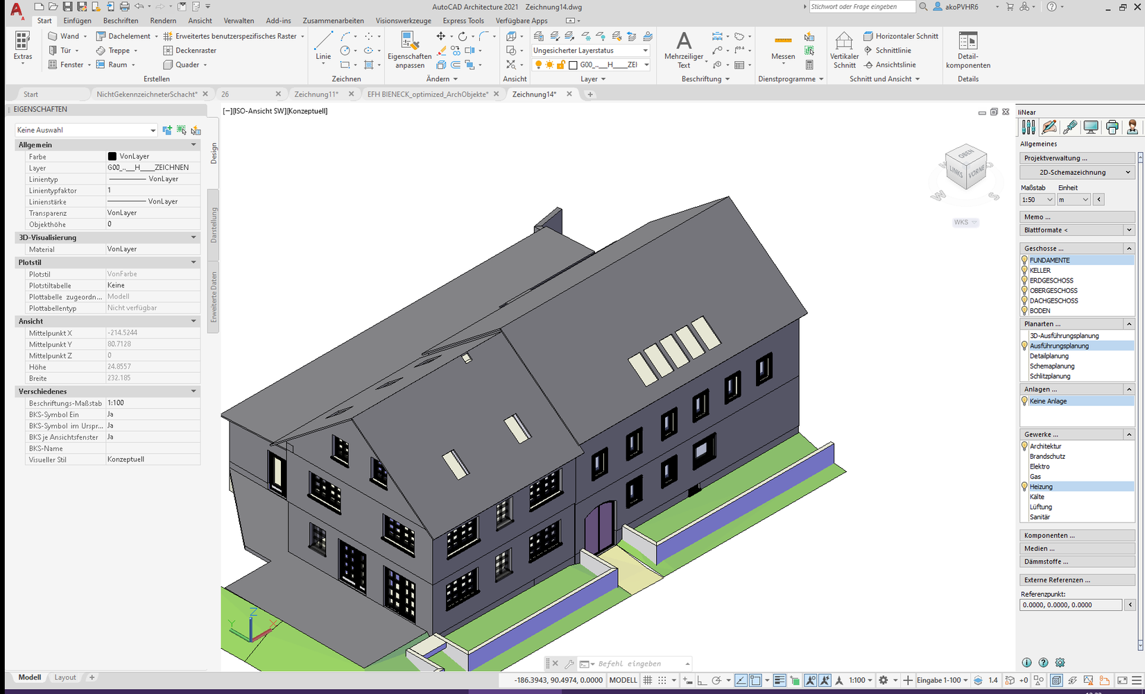
All this has already helped us in Revit to decide to prefer linked IFC models over imported ones, since for the building analysis use case geometric correctness is more important than parametric editability of the models. Under AutoCAD we are now going the same way. Instead of "recreating" the model with walls, windows, and doors, we use AutoCAD 3D modeling to create an exact replica of the architectural model. We have already taken this step with version 21 in addition to the known variant, but without being able to analyze this "exact model" yet. Up to this point, it "only" serves as a reference for further MEP modeling of technical control centers, air duct and piping systems (see Fig. 1).
This is where our next generation of building analysis comes in. The new algorithm is independent of the underlying data model. It can be used for all models as long as they provide semantically correct surfaces in three-dimensional space. To put it simply, the algorithm only needs to know two things: Where is the surface and what is the surface: Does it belong to a wall, a window, a floor, or a definition of space? Not much more is needed!
ONLY NEWER OR ALSO BETTER?
Not all that is new is necessarily better. I'm sure everyone can think of a few examples. If you are honest, sometimes this question cannot even be answered without a doubt. New things can have advantages, but also disadvantages. So, it depends on what prevails. We did not take the decision to develop a new, elaborate algorithm lightly and tried to sound out the advantages and disadvantages beforehand. To be able to present the decision to you in a comprehensible way, we still must briefly point out the actual difference. Considering a central problem with the following question: "What wall structures and what rooms are behind this wall surface?", then this question is approached by the algorithms in this way:
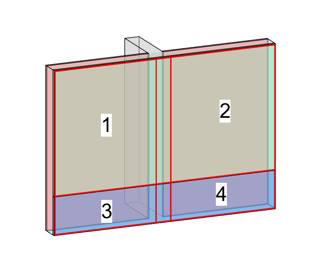
While our previous analysis looks through wall surfaces selectively to see what is inside and behind them, the new implementation checks all surfaces parallel to the examined wall (other rooms, component layers, ...) and determines a set of potentially different superstructures by creating intersections with all these surfaces (see Fig. 2).
The new algorithm is thus more reliable in the analysis since no surfaces can be missed and no difference in the component structure remains undetected. However, this method is much more time-consuming and "suffers" more from existing but possibly unnecessary details. Thus, in addition to a suitable database, intelligent optimization mechanisms are required to avoid losing acceptance due to long analysis times and small-scale results.
Another advantage of the new process is the ability to work directly with the room definitions provided by the architect - regardless of their complexity. It is therefore not necessary to import or redefine rooms and, if necessary, to live with the disadvantages or inaccuracies of the room definitions in the target system. Troubles with "not perfectly closed wall contours" and similar small discrepancies in the architectural model are now also a thing of the past.
WHAT ARE OUR REQUIREMENTS FOR BUILDING MODELS?
The requirements for a building model to be analyzed are always the same, regardless of whether you are working in the context of native modeling, i.e., "closed BIM", or receive the model via transport format, i.e., IFC.
With IFC, one more step has to be taken to get to this model: The correct setting of export options in the architecture software. Let's start with the general requirements for a model:
- The model must have defined spaces. Spaces are the starting point of any analysis. Consequently, it is imperative for an overall consideration that all building areas are "filled" with spaces. In early stages of planning, it is quite sufficient to define large areas or zones as "spaces". A smaller-scale consideration is only necessary when real room loads are required.
- the model, larger shafts must be identified as such. Not every slot or recessed gap in a wall for the drainage pipe needs to be marked, but the elevator shaft or the large shaft for the air ducts do. One reason for this is the easier detection from the "exterior": If there is no other room and no shaft behind a room surface, then it’s the "exterior". This can lead to incorrect readings in the absence of marked shafts. Another reason, of course, is the thermal consideration of these unconditioned areas. Marking the shafts is a task that is usually not done by the architect. Therefore, we offer tools on each platform that allow you, as a professional planner, to perform the definitions. These definitions are designed to remain valid even after the building model has been updated. Assuming the shaft still exists at about this location.
- A correct classification of the components is important for the comprehensibility and processability of the analysis results. It is not necessary that a wall or a window is "real", i.e., native architectural entities in the target system, it must only be defined on that spot so the machine can read in what the components represent. This is because a glass surface is initially difficult to distinguish from a concrete surface for the building analysis. It simply detects that the "wall structure" at the location of the window is different to the rest of the wall.
- the graphical detail for the analysis should be chosen reasonably. Modeled roof tiles, chamfers on concrete edges or fall protection on exterior windows are examples of nice details in the building model, but they are not very useful for building analysis. Interior finishes, such as baseboards, switches, and sockets, may also not be included in the analysis. Room boundaries should not depict every wall niche and tile joint but should have only as many individual surfaces as are necessary. Modeled door and window handles and frame details, on the other hand, do not interfere with the analysis because they are not used for it.
In addition to these general requirements, there are a few other things to consider when using IFC. Whether you use IFC 2x3 or IFC 4 for the export is of minor importance. The format specifications required for our use case are already all covered with IFC 2x3. The following aspects are more important:
- The correct "MVD" (Model View Definition) should be used. The MVD defines what is to be included in the IFC and how it is described. In case of IFC 2x3 it is the "Coordination View" and in case of IFC 4 the "Reference View".
- Openings (windows/doors) must be referenced via "openings" in walls
- The room boundaries must be included. It is important to export the "first level boundaries" - i.e., the simple spatial boundaries (six faces in the simple rectangular space).
- IFC4 can also transport "second level boundaries" - i.e., spatial boundaries already divided between neighboring spaces. This is usually implemented very poorly by the authoring environments, so our algorithm calculates this information independently in every case.
- correct convertibility of the component types to the associated IFC classes must be ensured. For example, have room boundaries been exported as IfcRelSpaceBoundary, walls as IfcWall, and "holes" for windows and doors as IfcOpeningElement?
- following graphical description types (Representation Type) for components and rooms are supported: SolidModels (SweptSolid, Brep, CSG, Clipping) and SurfaceModel (Tesselation). These are the common types that can be used to map all the essentials.
- Aligned project coordinates. Less important for the initial analysis, but even more important for coordination tasks in the further course of the project. Set them to a coordinate system. This means a "zero point" and an alignment of the building model.
With common professional architecture programs, all this is usually feasible at the "click of a button", though perhaps not on the first try. A coordination phase in which the various export options are tried and compared should always be scheduled.
CAN BUILDING MODELS DELIVER EVEN MORE (USEFUL) DATA?
The building geometry and its topology (adjacent rooms, shafts) are the most important data to extract from an architectural building model. In addition, a model can carry further information - also increasing in the planning progress - which can be directly incorporated into the load analyses. Among others:
- material information. The exact construction of walls, ceilings and roofs can be supplied directly in the model. Ideally, the structure is already modeled. This means that the individual component layers are available with their specific layer thicknesses. In this way, even difficult situations such as partial clinkering can be cleanly identified.
- Terrain data. From the simple input of a ground elevation to fully modeled terrain topologies, the information is used to determine the parts of the building that border the ground on the outside.
- Target states, i.e., data such as the target temperatures for heating and cooling agreed with the building owner, but also the required air conditioning can be anchored to the zones or rooms of the model.
- Loads, such as from persons, light or machines, can be stored via specific data or - depending on the platform - room profiles.
If this information is not stored in the model, it is captured in LINEAR Building by simple means. The data detected in this way continues to exist even after updates to the building model and does not have to be detected again and again.
However, they can be supplemented or overwritten at any time by data from the model as soon as the latter provides reliable information.
USE CASES TODAY AND TOMORROW
At the time of this article's publication, the new algorithm has not yet been released for productive use. We still must bring it to product maturity with models from everyday planning. Those of you who would like to contribute - especially with models from real projects - are cordially invited to contact us at preview@~@linear.de.
The first use case will be the IFC link for AutoCAD users. In the next step, we will also switch the well-known analysis of AutoCAD architecture models to the new algorithm. These models still remain the first choice for projects that need to do without (good) 3D models from the architect and where the specialist planner quickly creates a simple analysis model using the tools of the building manager.
In the final step, we plan to merge the new ideas and possibilities with the specifics of Revit-based building analysis to meet the highest quality standards on all platforms.
In addition to the obvious advantages of the new algorithm itself, cross-platform use allows us to implement and provide enhancements and customer requests for all users in one step.
Javier Castell Codesal