Details on Output
Information on Output.
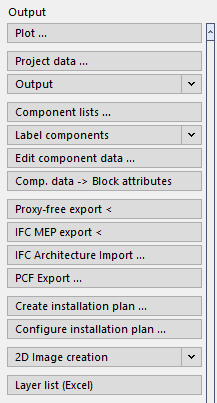
Plot
Opens the Plot dialog, where you can create a plot of a layout or drawing area.
Project data
If project data is to be output in the printout, but this data has not been entered in the Project administration, you can enter the most important data here, such as the building owner, planner and project address.
Output
The Output command allows you to output further drawing information, such as component lists or a quantity takeoff for ducts in different formats. These can be printed out directly or exported to another program.
Component lists ...
Opens the Component lists dialog. Component lists process component data for displaying and outputting data in tabular form, for adding/changing data directly, and for exporting/importing data using Excel for external supplementation or change. By importing you can, for example, import room log books into building models.
Label components
In the Label components section, you find the commands and settings for labeling components. Labels that you have created from component lists are also available in this section.
Edit component data ...
With this command you can read out the attributes of individual components. The read out data will then be listed in the Component data dialog and you can edit them and add new attributes. This is possible for all CAD elements. This metadata is used, among others, for the export commands IFC TGA Export and PCF Export.
Component data → Block attributes
This command performs a proxy-free export and is used to convert the component data assigned with the Edit component data command into block attributes. By this means, the drawing may be analyzed, e.g. by a facility management software. This process is not reversible. The program will thus create a new file for which you may define a name and a storage location.
Proxy-free export <
This command converts LINEAR objects into standard CAD objects allowing you to pass the drawing to other CAD systems and display the objects correctly. This applies in particular to objects that you created using the 3D Air duct, 3D Piping, 3D Electric cable trays and 3D Construction modules. The proxy-free export cannot be undone. Therefore a new drawing is created and the origin drawing will be closed. The proxy-free export may also be run for several drawings simultaneously. To that end, it is suggested to close the drawings.
IFC MEP-Export
During LINEAR the IFC MEP Export, LINEAR objects of the modules Design 3D Pipe&Power, Design 3D Ventilation, Panel heating/cooling systems including all system and calculation data as well as the architecture (AEC walls) are detected. Besides the 3D model also the corresponding metadata is exported.
IFC Architecture import…
With IFC Architecture import, you can import architectural models from an IFC file.
PCF Export ...
The PCF file format is a transfer format for isometric generation for manufacturing and installation in plant engineering. Use the PCF Export ... command to export 3D pipes to *.PCF format for transfer to pipe static programs. It is possible to export individual pipe runs, the entire system or individual components.
Installation plan (3D Front-wall installation)
This command automatically creates new layouts from drawn installation walls with sheet frames and title block at a scale of 1:50.
Create installation plan ...
Once the system has been divided into spools and assemblies and positioned, installation plans for the spools and assemblies can be created.
Configure installation plan ...
Once you create a system with Design 3D Pipe&Power, you can use the Create installation plan ... command to automatically generate detailed plans as separate layouts from individual system sections. The created installation plans can contain multiple views in different scales, isometric views or even position lists. The different views can automatically be dimensioned and labelled. The design, information content and the level of detail of these plans can be adjusted and administered within individual layouts in a template file.
You will find the MontageVorlage.dwg layout template in the program directory under: …\CAD\Basis\User-Standards.
If your software is from another manufacturer, you will find the layout template file in the program directory under : …\Basis\User-Standards.
Change layer structure
Using this command you can assign objects to another layer. In the following example, pipes are accidentally drawn in the Heating trade with the Supply medium and not in the Sanitary trade with the Cold water medium.
2D Image creation
This command creates 2D-images from individual or all viewports of a 2D-layout, consisting only of simple lines. You can use them for passing on revised drawings or plotting in 2D style (with hidden edges).
The image creation in large drawings including many objects might take a lot of time. Then it is recommended to restrict the 2D-image creation to a cut out of the drawing. Canceling the image creation is possible at any time using ESC.
The settings of the viewports, such as layers and sectional planes are respected. The color and the line type of the hidden lines can be configured.
Layer list (Excel)
Using this command you can have a list of all layers contained in the current drawing created in Excel, provided that the program is installed on your computer. This function excludes the layers of external references.
Label (3D Front-wall installation)
If an installation wall has been created and provided with item numbers, here you have the option of printing labels for the individual components of the front-wall. The labels are used to provide the individual mounting rails with the associated data, e.g. item numbers.
Label (only 3D Front-wall installation)
Label the furnishings or Steptec modules in your drawing.
Refresh item numbers (only 3D Front-wall installation)
If you made changes to the front-wall constructions that require new or changed item numbers, you can have them refreshed before creating the installation plan.