Details on 2D Image Creation
Information about the 2D Image creation command under Output.
This command creates 2D-images from individual or all viewports of a 2D-layout, consisting only of simple lines. You can use them for passing on revised drawings or plotting in 2D style (with hidden edges).
The image creation in large drawings including many objects might take a lot of time. Then it is recommended to restrict the 2D-image creation to a cut out of the drawing. Canceling the image creation is possible at any time using ESC. The settings of the viewports, such as layers and sectional planes are respected. The color and the line type of the hidden lines can be configured.
You are here:
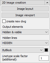
Image layout
Click the Image layout button to create an image from all the viewports included in the layout.
Image viewport
Click the Image viewport button to create an image from a certain viewports.
create new dwg
Select this option if you would like to create your own dwg files the image during creation.
Output elements
Select whether only the visible elements, only the hidden elements, or both should be taken into account when creating the image.
Hidden lines
Use the two drop-down lists and the color button to set the line style, color and line thickness of the hidden lines. Using the additional line type scale factor, fine adjustments of the line display are possible.
Linetype scale factor (additional):
The line type factor controls the representation of a dashed line. It is calculated automatically during image creation. You can use the additional line type factor to make fine adjustments to the representation of hidden lines. The default setting is 0.25. Multiple decimal places are possible.