
We start in an early design phase, when no building model is yet available, and then move on to model-based design, bill of quantities for detailed planning, and the creation of a file for the production of the duct components.
"Just" a Room Book?
Even in the very early stages of the MEP design, a room book containing the most important information is often available as a result of the requirement analysis. Starting with the rooms, structural information is provided, such as building parts, storeys, (rentable) units such as apartments, office wings, (medical) departments, and more. Additionally, there is information about room areas, target temperatures, (roughly estimated) loads, occupancy, and so on.
A room book like this can always be converted to Excel spreadsheets via room book synchronization as the smallest common denominator. This makes it possible to set up entire LINEAR Building projects in five minutes and develop further load calculations, initial design concepts for energy transmitters, and schematic system concepts for most trades.
In the case of ventilation design, the required air volumes in the respective rooms can be determined in the Ventilation module. Based on the room type, the applicable guidelines are set and, if necessary, the requirements are adjusted. Depending on the calculation method and the level of detail of the available information, further requirements for use may already be added. The level of detail therefore ranges from area-specific information to detailed load specifications for kitchen appliances or swimming pool equipment.
In addition to the Excel room book import, the air volumes can be further structured with the new Room Data Sheet Module (publication with Version 26): For example, by adding shafts and/or zones as additional structural parameters, the air volumes can be easily distributed to them in LINEAR Building. These values can then be used for an initial determination of the space requirements in shafts and distribution areas.
Last but not least, these settings and results can be synchronized back to the Excel spreadsheet and shared with the other project participants.
Break of Medium when switching to model-based working?
As an extension to the previous chapter, it should first be mentioned that it is also possible to start directly with a building model (Revit, IFC, AutoCAD architectural model). Instead of the Excel room book synchronization, the building project is then initially transferred from the CAD program. The rest of the process remains the same. It is then also possible to output the results into an Excel room book.
Assuming that the workflow began early with the room book and that a CAD model is only available at a later stage, Building then simply switches to the CAD model at this point. It is therefore not necessary to start planning from scratch. This prevents the dreaded loss of information due to a break in medium when switching between design phases. Of course, it is always possible that different information may be available when changing media in this way. Typically, the room areas and volumes in the CAD model are more accurate than the target values or assumptions in the room book. However, CAD models often lack information (metadata), such as the occupancy of rooms or target temperatures. So when synchronizing with CAD for the first time, pay attention to who is bringing which "true data". For typical cases, synchronization settings are already provided that do not "break" anything and only add missing data. You can find more information on this in the following box.
Model-related Data generated efficiently
It makes sense to keep all model-related data centralized in the model, where it is considered secure. This is especially true when it is hosted as a central model “in the cloud,” accessible to all those involved in the MEP design. Nevertheless, it is often more efficient to enter or detect this data outside the CAD environment. In the case of LINEAR Solutions, LINEAR Building is available for this purpose, with its load analysis options, design modules, and Room Data sheet module. For this purpose, LINEAR Building offers configurable parameter synchronization, which ensures that the model-related data is available in the CAD model at all times, but that the calculation or data input can be carried out as efficiently as possible.
The default setting for parameter synchronization is already configured so that an automatic mode is activated for a growing number of parameters (“Import/Export”), which automatically detects on which side adjustments have been made. For other parameters that are mandatory or typically detected by the model, the setting ensures that they are only transferred from there. And vice versa.
This way, we ensure that the CAD model remains the basis for model-related data, but that data generation can still be carried out in the most efficient manner possible.
Once synchronization is complete, the required air volumes are available as parameters for the rooms. LINEAR Building may have updated these again based on the room volumes from the CAD model.
For the next step, you now have to make a decision, just like with IKEA assembly instructions: If you want to continue with the classic design workflow, you can simply skip the following chapter, “The early design routing concept.” If you want to be inspired by the possibilities this approach offers, just keep reading here.
The early Design Routing Concept
It can be worthwhile to carry out initial pipe routing design at a very early stage, especially if other MEP systems can be considered at the same time. The aim of this design is to communicate space requirements: How much space is required in the heating center? Is it better to locate the ventilation center on the roof or in the building? What is the optimum number and size of shafts required? How can I make use of the space available in the supply routes under the ceiling? These and other questions should be addressed early on.
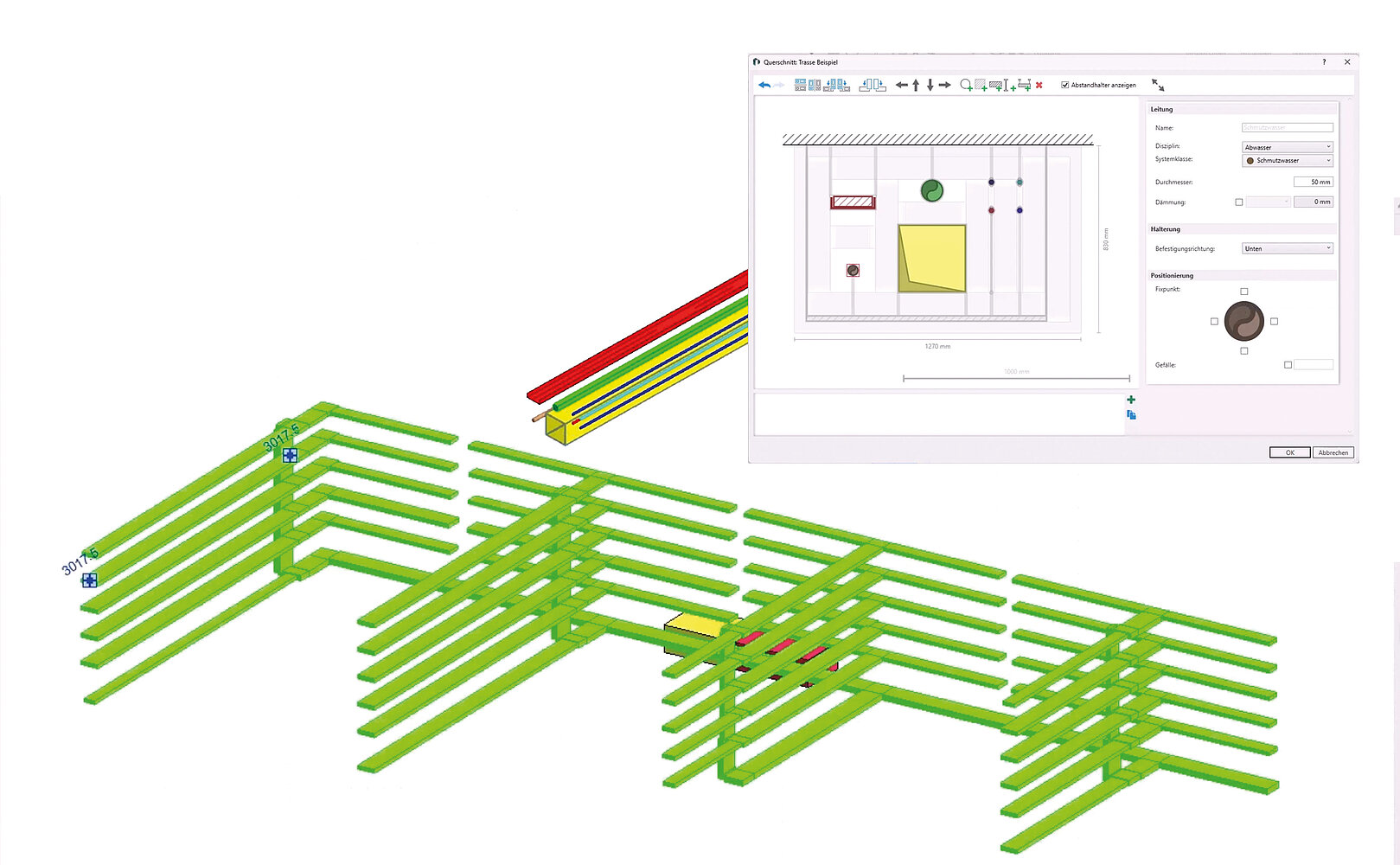
With the traditional method, this seems to be quite time-consuming, of course, as it requires a large part of the planning to be done (too) early on. The routing design tool offers exactly the right tool for this purpose: Without modeling individual ducts and pipes, it is possible to place large, easily defined pipe routes through the building. These already contain piping information for all relevant disciplines and show the total space requirements.
The loads of the individual media required for preliminary dimensioning can be easily found either in the room data sheet from Building or in the parameters available for the rooms. No appliances such as radiators, surface temperature control, air vents, or sanitary equipment are required. Upcoming enhancements to the pipe route concept will simplify this task even further by automating the collection of loads, including simultaneous approaches.
The great advantage of this type of design: The routing sections are detected very quickly in the schematic cross-section editor for the route elements. There is no need for three-dimensional (re)positioning of the individual pipes. This means that changes to requirements or plans can be implemented very quickly.
Communicating the results of this early design with the other project participants is an important part of this design phase. In addition to providing the pipe route model (either in the central model, as a Revit file, or as an IFC file - depending on the methodology), the Tasks and Reports module also provides coordination tools that can perfectly communicate coordination requirements via the BCF concept.
Another worthwhile tip: The effort that went into the routing concept can also be put to further use here: The routed elements can be converted into individual pipes and ducts at any time. The generated elements can then be used seamlessly for the more detailed design phases. No loss of information due to breaks in media!
Modeling the Duct Network
The next step is to place the air outlets in the rooms. Now you have to choose between different options: If an open installation with ventilation grilles in ducts is to be used, the corresponding ducts are placed first. You can use the integrated ductulator (again) for preliminary dimensioning of the ducts. Otherwise, the air outlets that are to be connected individually later are placed directly.
In both cases, the air outlets/ventilation grilles are selected either as neutral components from the library or directly from the manufacturer-specific LINEAR CAD Browser or Content Hub (see box “Ventilation Components with 'better' Data”). There are advantages and disadvantages to both options that should be considered. The advantages of manufacturer-specific selection include the certainty of installing the correct dimensions from the start, being notified of any potential problems with the air outlets in the event of deviating volume flow rates at a later point, and, depending on the component, also receiving the corresponding setup values for balancing. With manufacturer-specific components, there are also more precise values for pressure loss and noise data. The neutral components are advantageous due to their neutrality. However, even with manufacturer-specific components, there are a few ways to “hide” their origin: For example, manufacturers often offer simplified geometries of their components that hide logos and very product-specific features. The visible properties and data can also be neutralized.
The upcoming version V26 will also offer the option of assigning manufacturer/product-specific information to neutral components. This allows the components to keep their neutral appearance, but still be included in the calculation with “real” data.
The selection itself is always made for manufacturer-specific air components using a design algorithm that requires the volume flow rate and the intended use (supply or extract air) to be specified. This ensures that the correct selection is made and also means that the components bring their own design flow rates directly into the building model, so that these do not need to be specified again.
For neutral air outlets, the volume flow rate is only specified after placement, for example via the LINEAR Properties. This can also be done for several air outlets at the same time, so that this step now takes very little time.
Changes to the flow rates in the event of changed requirements can be made in the same efficient manner for all types of air outlets (including manufacturer-specific ones). It becomes even more efficient if you use the element lists (LINEAR for Revit) or the component lists (LINEAR for AutoCAD) for these tasks. Here, powerful filter options can be used to quickly edit similar air outlets together.
If an acoustic assessment of the system is also to be carried out, the room type and shape can be assigned for ventilation in the same way. Although the room shape is determined automatically for most rooms, manual specification is required for more complex geometries. All information required for acoustic assessment, such as reverberation time, absorption area, and permissible sound pressure level, is determined from these two specifications.
Ventilation Components with “better” Data
The most important manufacturers of ventilation components are already integrated into LINEAR Solutions, either via VDI3805 data sets or via direct connection to manufacturer software or websites: The components are available with their geometry for all CAD platforms as well as with their technical data. A special feature of integration into LINEAR Solutions is that the components not only provide the data for design, but also all data for the entire application. Changes to volume flow rates therefore automatically lead to changes in sound and pressure data and, depending on the component, may also lead to changes in (damper) settings.
However, it would be presumptuous to claim that the available components are enough to make everyone happy. Something is always missing. Even if it's just the preferred manufacturer for special components or the manufacturer that is the top dog abroad. Of course, we would also like to be able to add this manufacturer to our portfolio (note on our own behalf: It helps us greatly if you would share your requests for missing components on the LINEAR IDEA CHANNEL.)
However, you do not have to wait until the manufacturer is ready. There is a solution for all manufacturer-specific components that cannot be selected directly in the software: In the data set entry section, you can add the missing data for the ventilation components yourself with just a few entries. All you need is the technical data sheet for the component and a few minutes to enter the information. You then simply assign the data set created like this to the neutral components, and you have real data that can be used for calculations.
Of course, the well-known Rooms dialog still exists, allowing you to configure all settings room by room. Although this may be less efficient, the dialog box provides a clear, compact detailed view of all room data with the associated flow rate data, including a target/actual balance of the volume flow rates.
If these are not already available as a result of the pipe route design, the next step is to model the shaft ducts and distribution ducts on each floor. For preliminary dimensioning, the total air volumes from Building and the integrated ductulator, calculated in storeys and/or zones and shafts, can also be used here if desired (note: A reasonably plausible preliminary dimensioning is entirely sufficient at this point. In later steps, the duct network calculation will optimize the dimensions if desired.) These ducts are then connected automatically to the air outlets at room level.
At this point at the latest, it is advisable to coordinate the Void planning with the other parties involved in the project. The module available for this purpose allows both the automatic placement of opening proposals (provision for voids) and their transfer to those involved in the p roject for review (BCF + IFC if necessary) and the withdrawal of accepted or rejected proposals (BCF). The collision check integrated into LINEAR Solutions recognizes accepted opening proposals and does not flag collisions as errors at these locations. This means there is no need to wait for an updated architectural model. If architectural and MEP design are carried out in a “closed BIM” context using Revit, LINEAR also provides a free tool for architecture that allows opening proposals to be converted directly into “real” openings in the architectural model. This means you receive an updated model at the touch of a button.
At the same time, a calculable network is now available. Even before fire protection devices, control components, and sound-absorbing components are installed, the duct network calculation should be performed once to check the dimensions of the ducts. If this results in deviating duct sizes, automatic redimensioning can operate more flexibly than if components are already installed in the ducts, especially when planning with manufacturer-specific ventilation components. Automatic redimensioning is of course also possible at a later stage, but may involve more manual adjustments.
Once the dimensions have been provisionally verified, the necessary fire protection equipment should be installed first. Their influence on pressure and sound can now be verified with a recalculation. The next step is to install control components and silencers. Both influence each other, as sound absorbers generate pressure losses that can affect the pressure balance, and control components influence sound development. Therefore, it is entirely possible that this step will have to be repeated a second time.
Provided you have some experience in MEP design, you will be able to select the components right away. In any case, the corresponding notes and warnings about pressure differences or sound level exceedances, which the calculation can output at any time, are helpful. The speed of the calculation has been optimized in recent years so that it can be carried out after each step for control purposes without taking up much time.
At this point, a balanced and acoustically functional duct network is available. If manufacturer-specific ventilation components have been installed, the settings for the adjustable components are also known. Otherwise, the pressure losses still to be compensated by the control elements are displayed.
The Material and its Costs
We haven't discussed the material and its costs yet. As soon as ducts are available, you can already perform a cost calculation based on a bill of quantities using the workflow described above. Even if you plan your networks using the single-line method, a bill of quantities can be created based on the calculated duct dimensions (see the box “single-line vs. Model-based Design”). Of course, it will be more accurate if you used a 3D model and determine the bill of quantitites based on that model. Especially if cost- or production-related details such as access ducts are also modeled.

Single-line vs. Model-based Design
Even though this article mainly describes the workflow for model-based design (Revit and AutoCAD), most of it also applies to single-line design with LINEAR for AutoCAD. Of course, a 100% accurate model-based bill of quantities cannot be performed on a single-line model, but the duct network calculation already provides a bill of quantities based on the calculated dimensions that is close enough to determine the costs.
In addition, the same manufacturer-specific ventilation components can be installed in single-line models as in 3D models. The accuracy of the calculation is therefore not a question of the design method either. A combination of single-line ducts and 3D components is also part of the concept!
Also: If the single-line model is only to be used in early design phases, it can be automatically converted into a 3D model at any time for further development!
At the latest when you want to transfer your MEP design to production, assigning item numbers is essential. The tools provided for this purpose allow you to do this with just a few clicks and preferences that can be preset. Last but not least, the design of the mounting is also an important part of the design process. LINEAR Solutions therefore provide the mounting options required for duct design, which can be added with minimal effort.
The Result
Although the result always comes at the end of a process, and in this case also at the end of the article, interim results must be communicated in every design phase, especially when applying the BIM methodology. What makes sense here depends on the design tools used by all parties involved, the methodology, and the purpose of the output. If a central model is used in a closed BIM context, outputs for coordination purposes are rarely necessary. Nevertheless, just as in the “open BIM” context, the exchange of BCF files can be useful here in order to specifically point out collisions and other problems or coordination requirements. In the “open BIM” context, the IFC format remains the gold standard offered for all platforms (even if the gold may occasionally appear dull).
It will certainly take some time before all professionals on the construction site are equipped with VR glasses. Traditional deigns with floor plans, sections, and detailed views are therefore still the first choice for communicating the results of planning – at least on the construction site. LINEAR Solutions offers a wide range of support options for the creation and management of these plans. From simple tools for generating cross-sections to detailing floor plans with riser arrows and much more, the plan creation process is made easier.
A new feature in V25.1 is ensuring now that plans are up to date. Nothing is more frustrating than incorrect execution due to outdated plans. Unlike VR glasses, every professional and even every assistant has a mobile device with a camera and (hopefully) network access at their disposal. With this, and with plans that are provided with the LINEAR QR code, everyone can check whether the plan they have in front of them still shows the latest status of the design. No more (which benefits IT security), but also no less (which saves the construction management a lot of phone calls and prevents incorrect construction).
Another ventilation-specific output format is the e-klimaX format, which contains manufacturing data for air ducts and can be processed by most duct construction companies. In many cases, it is even automatically “fed” directly to the production machines. However, this only works well if the duct components comply with the relevant standards. Special fittings, for example, for particularly narrow, tricky, or flow-optimized situations, must still be delivered manually to the duct construction company with dimensioned detailed drawings. Since this effort is rarely proportionate to the benefits and costs, here is an appeal to ventilation designers: Try to avoid using special fittings, even if they sometimes seem more convenient during design. In many situations, flow optimization can be achieved satisfactorily by combining fittings (keyword: Combi Frame).
Being Spoilt for Choice by Revit
When designing with Revit, there is one special feature: The selection of the families to be used.
Since LINEAR Solutions are generally open to the use of your own or purchased families, this is of course also possible with duct fittings. However, for a bill of quantities in accordance with current guidelines, these must be build in such a way that the necessary parameters (a, b, c, ... f) can also be retrieved. To do this, the algorithm already uses some heuristics to find the right parameters. Since this is not 100% accurate unless the name is specified precisely, this program selection must be confirmed manually once. If the program cannot find suitable parameters, these must either be assigned manually or derived from the corresponding parameter in the family itself with a unique name.
This does involve a one-time manual effort, but it is well worth it because:
- This allows families of choice to be used.
- This prevents breaks in media (redesigning) when projects are taken over from other parties.