Details on Component Data for the Partial Network End
Information about the dialog for component data for the partial network end.
The partial network end has only one connecting point which has to be connected to a pipe.
There are the following ways to use the partial network end:
-
Not connected, as a placeholder for a single consumer that may be relevant for flushing.
-
Not connected, as a placeholder for a non-constructed subnetwork, which may contain a flushing-relevant consumer.
-
Connected to a partial network start, where the partial network start represents the beginning of a partial network with other consumers.
You are here:
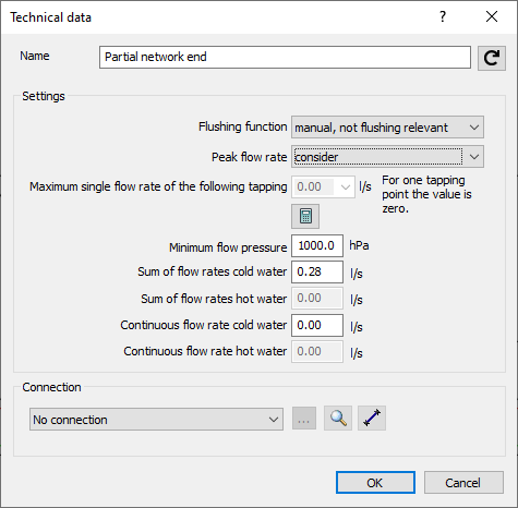
Partial network end as placeholder for single consumers that may be flush-relevant
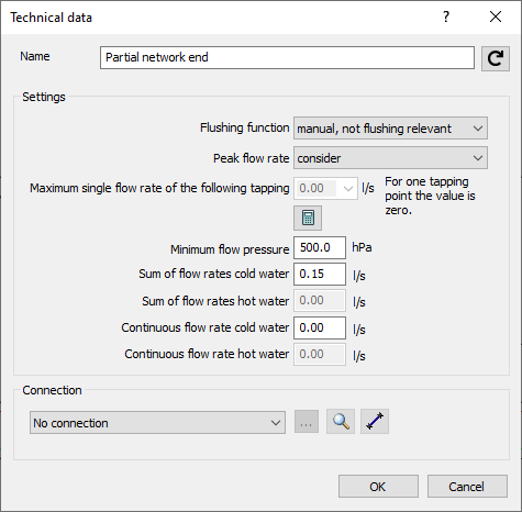
Name: Specifies the name of the component. You can modify the name. Clicking  restores the default setting.
Settings
Flushing function: Determines whether the partial network end is used as a placeholder for a flushing-relevant or nonflushing-relevant single consumer, and thus whether a flow divider is taken into account in the calculation. A consumer that is actuated at least every three days and thus initiates a water change in the entire flow path is referred to as flush relevant.
Peak flow rate: Determines whether the partial network end is considered as a placeholder for an individual consumer in the peak flow or not.
Partial network ends as single consumers, whose peak flow rate is not taken into account, are additionally included as a partial flow. The single consumer flow which is determined from the disabled flows is considered for dimensioning when it is greater than the calculated peak flow rate according to building setting. In this case a note is issued in the Report dialog box. The simultaneity in % (Data Coloring) will consider all connected consumers; also for those where the peak flow rate is not considered. Therefore, the percentage becomes smaller in these cases.
Max single flow rate of the following tapping points: If the partial network end represents a consumer, do not enter a value here and leave 0 l/s standing. The sum of flow rates will then be used for calculation.
 : Opens the Flow rate in partial network dialog, where flow rate and minimum pressure can be set using standardized consumers.
Minimum flow pressure: Enter the minimum flow pressure in hPa.
Sum of flow rates Cold- and Hot water: The sum of flow rates is to be entered at sum of flow rates cold- or hot water, respectively. Automatically, only the value is considered that matches the connected pipe (hot or cold water).
Continuous flow rate Cold- and Hot water: If you want to assign continuous flow to a consumer, you can do so at Continuous flow rate cold or hot water. If at the same time you entered a calculation flow rate, it will not be considered anymore. A message will be issued accordingly.
Connection: If the partial network end represents a single consumer, no action is required.
Partial network end as placeholder for a non-constructed partial network, which may contain a flushing-relevant consumer
Name: Specifies the name of the component. You can modify the name. Clicking restores the default setting.
Settings
Flushing function: Determines whether the partial network end contains a flushing-relevant consumer as a placeholder for a non-constructed partial network, and thus whether a flow divider is taken into account in the calculation. A consumer that is actuated at least every three days and thus initiates a water change in the entire flow path is referred to as flush relevant.
Peak flow rate: If the partial network end represents a partial network, but it has not been drawn, you can only exclude the entire partial network from the calculation of the peak flow rate. Select the do not consider limits option to do this.
Max single flow rate of the following tapping points: If the partial network end represents a network with several consumers, enter the largest of all flow rates from these consumers. This flow rate will be set to be the minimum for the respective flow path.
: Opens the Flow rate in partial network dialog, where flow rate and minimum pressure can be set using standardized consumers.
Minimum flow pressure: Enter the pressure in hPa to be used for the partial network and its pipes.
Sum of flow rates Cold- and Hot water: Enter the sum of flow rates at sum of flow rates cold- and hot water as a sum of all consumers of the partial network. Automatically, only the value is considered that matches the connected pipe (hot or cold water).
Continuous flow rate Cold- and Hot water: If you want to assign continuous flow to the partial network, you can do so at Continuous flow rate cold or hot water. If at the same time you entered a calculation flow rate, it will not be considered anymore. A message will be issued accordingly.
Connection: If the partial network end represents a partial network that has yet to be drawn, no further action is required.
Partial network end linked with partial network start
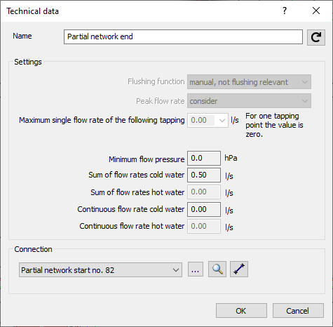
Name: Specifies the name of the component. You can modify the name. Clicking restores the default setting.
Settings: If the partial network end hast been connected to another partial network, the section for settings is deactivated. The necessary values are taken from the partial network and used for calculation.
Connection: Drop-down list to select the partial network start to be connected. You can either click to select a partial network start from the drawing or to select an available partial network start from the list of available partial network starts. A partial network end can always be linked to exactly one partial network start. A partial network start in turn can be linked to several partial network ends. You can use such an n:1 connection, for example, to draw a bathroom in residential construction only once and then link it several times in the floors. Unfortunately, an n:1 connection is only possible for hot and cold water pipes. Click  , zooms in the linked partial network start in the drawing.