Details on Component Data for Pipes
Information about the component data dialog for pipes.
Pipes are always drawn as lines in the drawing. The program recognizes the line type (cold, hot water or circulation, etc.) by the layer on which these lines are located. A pipe may be connected at each end to a maximum of three other pipes (crossover T-piece) or a block symbolizing another component. It is neither possible to connect several pipes to a component connection nor to leave pipe ends open. Fittings (elbows, T-pieces) have to be inserted or manifolds have to be placed at branches. For open pipe ends use the component pipe end.
The pipe type is either determined by the default settings which you can specify in the Pipe tables or by the separate definition of the pipe.
You are here:
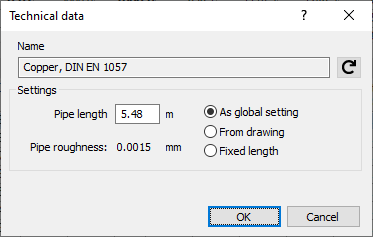
Name
Shows the name of the component. You cannot modify the name.
Settings
Pipe length
Here, the drawn length is displayed. You can change the value manually and have it reset to the drawn length by clicking From drawing.
As global setting: The length setting is based on the setting made in the Settings. For the length, the setting As global setting is preset.
From drawing: The current lengths from the drawing are always used. The factor for taking over the pipe length from the drawing is the same for all pipes and is also defined in the Settings dialog.
Fixed length: This option is used to keep the lengths you enter as fixed values, always.
Roughness
The specified Roughness is the value taken from the relevant pipe table.