Details for Room Contours, Building Contours
Information about Room and Building Contours on the Create tab in the discipline Architecture.
You are here:
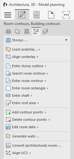
Storeys...
The Storeys... section displays existing storeys. Clicking the Storeys ... button opens the Storey table dialog where you can parameterize the storeys and import storey data.
Load underlay ...>
This command allows you to insert files in DWG or PDF format as well as image files into the drawing. These files are assigned to the current drawing as an external reference.
If you would like to insert several underlays at different heights, you should create a Table of storeys beforehand and set Storeys on upon the other in Drawing type.
If you would like to insert several underlays at the same height next to each other, you should first set the Drawing type to Storeys side by side.
Align underlay <
This command allows you to rotate and scale the underlay to the correct size at the same time. This command is particularly useful to adjust and align scanned plans. Since the horizontal scaling (x-axis) and vertical scaling (y-axis) are queried, even compressed or stretched external references may be straightened again.
Enter storey contour < / Enter room contour < / Enter room rectangle <
In order to generate 3D walls on the basis of the 2D template, you will have to define these walls by tracing the storey and room outlines. This is done using the commands Enter storey outline and Enter room contour or Enter room rectangle.
If you want to define shafts without room data and labels, which are also not transferred to LINEAR Building, use the command Enter Shaft <.
Do not use the Enter room contour < and Enter room rectangle < commands to subsequently define rooms in the drawing that are not defined by IfcSpaces in the IFC file. For the building detection based on an IFC link it is necessary that all rooms are defined as IfcSpaces, so that the rooms including all data and components can be transferred correctly to LINEAR Building. If your IFC file contains rooms that are not defined as IfcSpaces, contact the responsible architect and ask him for a correction.
Search room contour <
In building detection, room information is no longer obtained from the three-dimensional walls, but also from the room contour, among other things. Therefore it is necessary to modify the room contours when walls have been moved or stretched, in order to detect the modified room using the automatic detection.
In the case of a room surrounded by three-dimensional walls, the Search room contour command automatically creates the room contour. Room contours can be stretched or modified as usual by using the grips or by means of the command Add contour points and Delete contour points.
Enter shaft <
You can define shafts using the Enter shaft < command. Shafts do not contain room data and can thus not have a label. They are not taken into account during Building detection and are not transferred to LINEAR Building. However, the adjacent situation of room components adjacent to such shafts is correctly passed to LINEAR Building.
If you want to define shafts with room data and label in an IFC Workflow, which are also transferred to LINEAR Building, use the commands Enter room contour < or Enter room rectangle <.
The Building detection in 3D and 2.5D model planning usually also detects rooms that do not contain openings, provided they are larger than 3m². This means is necessary to detect rooms such as attic or basement rooms, which can be accessed solely via a staircase. In order to avoid detecting any large shaft as a separate room, you may define such as actual shafts explicitly.
Enter roof area <
First define the roof area and then generate the walls. Thereupon, the walls will be adjusted correspondingly and be shortened or chamfered. After having generated the walls, the roof areas may not be deleted. Otherwise the automatic detection and the data transfer to LINEAR Building will not work correctly.
Before starting the Enter roof area command, the course of the roof area should be known. Each sloped plane is a roof area on its own. Thus, a gable roof consists of two separate roof areas.
The first three roof area points require heights that define the slope. For the other points of the roof no heights are required. Therefore make sure you know the heights of the first three definition points.
Add contour points <
You may add contour points to previously traced storey and room outlines or you may delete them in order to incorporate plan modifications into your drawing easily. If the modifications of a room shall be regarded by the automatic detection it is necessary to adjust the room contour, too.
Delete contour points <
You may add contour points to previously traced storey and room outlines or you may delete them in order to incorporate plan modifications into your drawing easily. If the modifications of a room shall be regarded by the automatic detection it is necessary to adjust the room contour, too.
Edit room data <
With the Edit room data < command, you can subsequently edit room data such as room name, room number or temperatures, specify the label used and place missing room labels. After activating the command, click a room label to adjust the room data or change the label in the Room data dialog. If you click a room contour instead of a label, you can then place the room label.
Generate walls ...
As soon as all relevant storey and room outlines and roof areas have been entered, the program may generate 3D walls automatically.
Convert (architectural) rooms ...
This command can be used to convert room objects in AutoCAD Architecture format (AEC Spaces) to LINEAR room contours. Subsequently, these room objects can be used for automatic building detection with LINEAR Building. The conversion is particularly useful when spaces already contain metadata. This is the case when spaces have been created by importing an *.IFC file.
Align UCS <
By using the Align UCS command is you may adjust the current user coordinate system. You may thus apply orthogonally orientated command such as Enter room rectangle and Enter shaft also to rooms which are not rectangular to the drawing surface.