Details on Options
Information about the Options dialog in the Building Manager.
You are here:
The settings you make here affect the building detection and are saved in the drawing. If you would like to change the dimensions for the wall thickness and the openings on a long-term basis, please make these adjustments in the drawing template.
Apply standard dimensions, Apply drawing dimensions
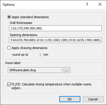
Apply standard dimensions
If you have used a scanned plan as a basis for creating the 3D model, the dimensions of the components will not result in standard dimensions, but corrupt values. If you activate the Use standard dimensions option, only the dimensions that are included here will be passed to the program LINEAR Building. If 360 mm is specified as the maximum wall thickness, all walls thicker than 360 mm will be detected with 360 mm wall thickness only. You can change and extend the standard dimensions for Wall thicknesses and Opening dimensions. The dimensions are saved in the drawing.
After transferring the data to the program LINEAR Building, a separate component is created in the master file data for each wall thickness. The U-values for these components then have to be defined. Therefore, the walls in the heating load and the cooling load are initially marked as faulty with an exclamation mark.
Apply drawing dimensions
If the drawing template has been created cleanly and few deviations in the dimensions are to be expected, activate the Apply drawing dimensions option. Specify how the dimensions in millimeter should be rounded when transferring them to the program LINEAR Building.
round to
Rounds the selected drawing dimensions to the specified value.
Room label
When entering the room contours with the Enter room contour < and Enter room rectangle < commands, the room is labeled. Here you can set which room label should be used for this. Click  and select the label in dwg format. The default room label GMRoomLabel.dwg is provided in the program folder in the path ...\CAD\GebaeudeManager\User-Standards. To create your own label, you can save the supplied label GMRoomLabel.dwg under a different name and then adapt it to your needs. If your software is from another manufacturer, you can find the file in the program directory under: …\GebaeudeManager\User-Standards.
Adjoining rooms/apartments
FL/CE: Calculate mixing temperature when multiple rooms adjoin..
For floors and ceilings, the adjacent temperatures are determined upwards and downwards. If there are several rooms with different temperatures above or below a room, you can determine whether a single floor or ceiling area should be transferred with a mixed temperature after the transfer into LINEAR Building from the rooms. The mixing temperature is determined per percentage of area from the adjacent rooms.
If the check mark is not set, a separate floor or ceiling surface is created for each individual adjacent room.