Details on the Parameter Manager
Information about the Parameter Manager dialog.
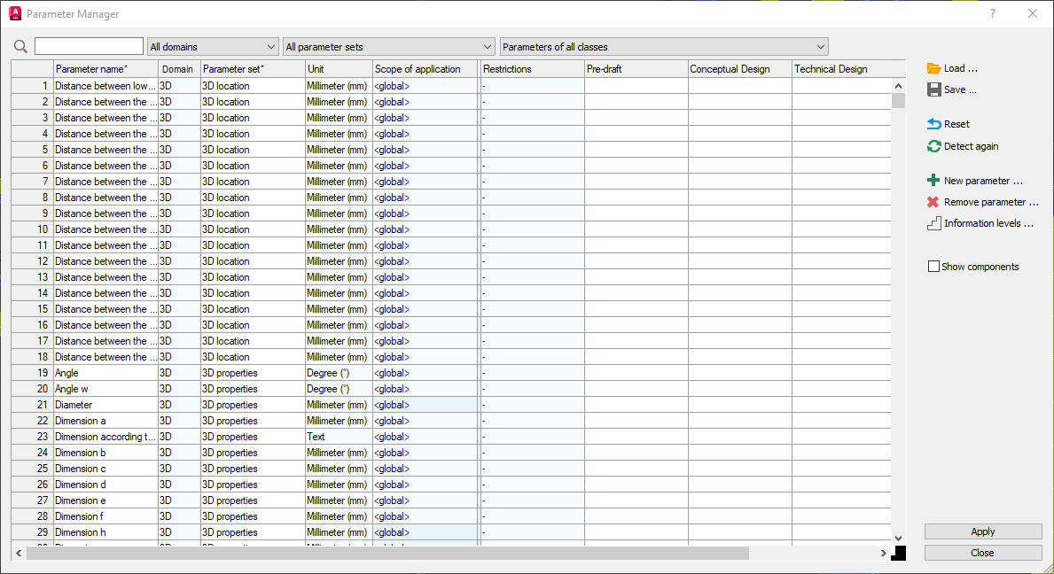
The Parameter Manager lists all LINEAR parameters and allows you to edit the parameters. Furthermore, you can define restrictions for the input of parameter values and assign parameters for the output of an information level. Parameters that are used by several component classes can be edited on a component class-specific basis.
You are here:
or

Search and filter functions for parameter management
Search field for parameter names
You can filter the parameter table by parameter name or by parts of the parameter names by entering character strings in the search field. The search starts automatically after you enter the first character and is updated after you enter further characters. Upper and lower case is not relevant.
 : Click on this button if the list of parameters has been newly entered or reset and you want to search or filter for the content still in the search field.
Parameter set drop-down list
Allows you to filter the table of parameters according to parameter sets.
Drop-down list of component classes
Allows you to filter the parameter table by component class and only display parameters that are used in the current drawing of components. You can also only display parameters that have already been adjusted.
Parameter management table
The table lists all LINEAR parameters and allows you to edit these parameters.
Context menus of the column headers
Right-clicking on a column header opens a context menu that you can use to sort the table in ascending or descending order and to reset sorting. Sorted columns are marked with an asterisk (*). In the columns of the information levels, you can also activate and deactivate the corresponding level of information for all parameters.
| Column | Description |
|---|---|
| Parameter name | Displays the parameter names and allows parameter names to be changed. Adjusted parameter names are displayed in bold. The original parameter names are displayed together with the ID of the parameter in the tooltip. Delete a changed parameter name to restore the original parameter name. |
| Parameter set | Displays the parameter set to which the parameter is assigned. All parameters are assigned to a parameter set according to their origin. Click on Enter an unused parameter set name to create your own parameter set. Delete parameter set names you have entered yourself to restore the original parameter set. The name of the original parameter set is displayed in the tooltip. |
| Unit | Displays the unit of the parameter and allows you to adjust the unit. Click on |
| Scope | Displays the scope of the parameter and makes it possible to exclude certain component classes from the general scope (<global>), e.g. to assign restrictions to them for entering the parameter values. The resulting scope is then displayed in a line below the parameter. 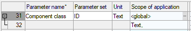 Clicking on If a parameter is not used by any component class in the current drawing, the cell is colored blue and the tooltip provides information about this status. For parameters that are used in the current drawing, the cells are not colored and the tooltip provides information on how many and by which component classes the parameter is used. For scopes that are excluded from the general scope of the parameter, the tooltip provides information on how many and which component classes are affected by the exception. |
| Restrictions | Shows whether and what restrictions there are for entering parameter values and allows you to define restrictions. Clicking on Values that do not match the specifications of a restriction are marked in red in the LINEAR Properties and Component lists. |
| Preliminary Draft, Draft, Execution | Information levels for the IFC MEP Export You can use the information levels to control the level of detail of the data to be output in the LINEAR Properties and in the IFC TGA export. For example, you can exclude parameters whose values are only required for execution planning from the information levels of other planning phases and thus always adapt the amount of data to be output to the current planning phase. Set check marks in the corresponding columns to assign the data of a parameter to an information level. In the IFC MEP export, you can then specify which information level is used for the export or whether the data of all or no information levels is used. If required, you can use the Information levels ... button to open a dialog in which you can edit and expand the information levels. |
 in a selected cell to open a context menu that you can use to assign a different parameter set to parameters. For parameters that have been assigned to another set, the name of the parameter set is displayed in bold. Remove bold formatted names of parameter sets to reassign the parameter to the original parameter set.
Further parameter management functions
Load ..., Save ...
Reset
Allows you to remove all defined settings and/or reset the parameter management to the default settings of the delivery status. After clicking on Reset, a dialog opens in which you can choose between the two options. If you have overwritten the DefaultParameterSettings.parset file of the default settings for the parameter manager and want to restore the delivery status of the file, select Reset to default settings in the dialog that opens and then save the file again under the file name.
Update
Updates the data listed in the dialog. Use this button, for example, if you have performed a calculation while parameter management is open and want to update the data determined during this calculation and written to the components in parameter manager or if you have changed the drawing.
New parameter ...
Opens the Select component classes for the new parameter dialog in which you define the component classes for the new parameter. In the Set parameters dialog, you can then specify whether a completely new parameter is to be created or whether an existing parameter for other component classes is to be used. Newly created parameters that are not based on existing parameters are automatically assigned to the Product information parameter set.
Remove parameter ...
For parameters that are used by component classes, opens the Select component classes in which the parameter is to be removed dialog in which you specify the component classes in which the parameter is to be removed. By removing all assigned component classes, you can remove self-created parameters from the parameter management.
Information levels ...
Opens the Configure information levels dialog, in which the various information levels are listed and you can edit and extend the information levels.
Show components
Enabled: All components that have a parameter of the currently selected row are highlighted in the drawing.
Apply
All changes are accepted and the dialog closes. The settings are saved in the current drawing.