Details on Components
Information about the Components dialog.
The program creates drawing elements that have certain functions, e.g. radiators, windows, insulation, ducts, etc. These elements are constructed on fixed component layers. The attributes for the available components, e.g. colors and line widths of the layers, are already defined and can be adjusted by you in the table. All settings you make here are saved in the current drawing. If you would like to change certain settings permanently, create a corresponding template file.
Changing the properties of components may affect certain program functions.
You are here:
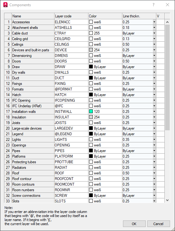
Name
The displayed names of the components depend on the loaded module.
Layer Code
In this column, simply click the appropriate field to enter or modify an abbreviation.
Color
Double-click in a field of this column to open the Select Color dialog. This dialog contains the Index Color, True Color and Color Books tabs. Each tab contains an extensive color palette from which you can select the desired color.
Line weight
In this field, use to the button at the right edge of the field to open the list and select the desired value.
V (Visibility)
If the components have been used in the drawing, this column contains the light bulb symbol which can be used to activate, and deactivate the layer.