User Interface
Explains the concept of the user interface in AutoCAD.
On this page you will get an overview of the individual components and the basic concepts of the user interface.
Overview
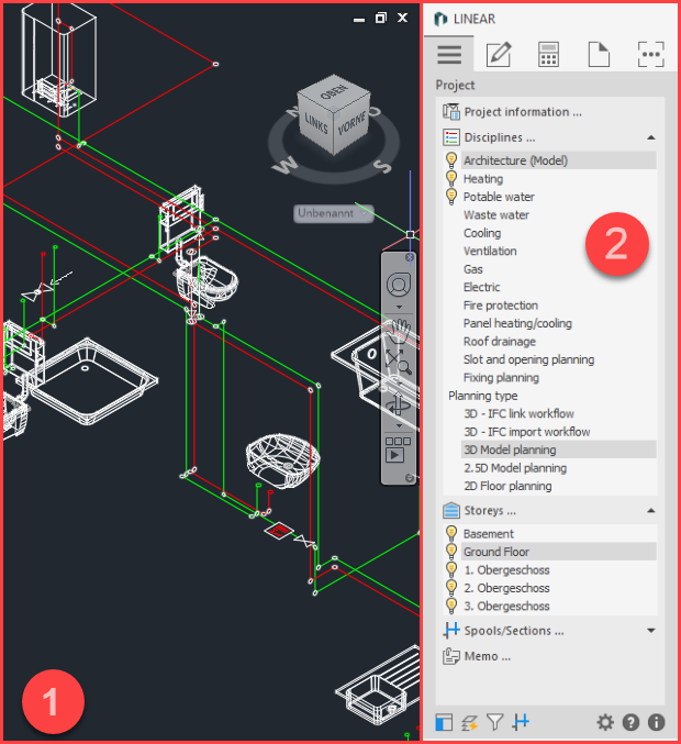
- AutoCAD drawing area - Area where you create your drawings.
- Control Board (CB) - The Control Board contains the five tabs of the LINEAR Desktop. Double-click in the title bar of the CB to undock and dock the board.
LINEAR Desktop Tabs
| Tab | Content |
|---|---|
 Project | Contains basic functions for setting up the project. You can enter project information, manage storeys and control the functionalities of the other tabs by selecting discipline and planning type. |
 Create | Contains commands for creating and editing pipe/duct networks. Also contains commands for creating and inserting manufacturer components. |
 Analyse | Contains commands for calculation and detailing of pipe or duct networks. |
 Labeling and Output | Contains commands for labeling, dimensioning, and outputting information from your drawing. |
 Tools | Contains a variety of tools, regardless of the discipline and planning type selected, that are not assigned to any specific workflow step and support you at various points during the editing process. |