-
Define the construction level and offset.
-
Click Discipline.
The configurators and families of the ventilation discipline are displayed.
-
Open the Configurators section.
-
Click Ventilation device ...
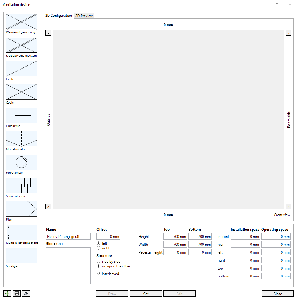
The Ventilation device dialog opens.
If no ventilation device family is loaded in the project, an empty template is displayed in the dialog.
-
Enter the name and, if necessary, a brief description of the ventilation device.
-
Define the Offset and Structure.
-
Enter the dimensions and any installation and operating spaces of the ventilation device to be taken into account.
-
Drag and drop the desired components into the workspace, 2D Configuration.
-
Select a placed component and specify Subtype, Length and the dimensions for the interference spaces.
-
If connections for the air duct are to be assigned to the component, click the
 button in the Connections tab.
A new connection is created.
-
Configure the form, position and dimensions of the connector.
-
Define all other components as described above.
-
In order to change the flow direction of the air in the device, if necessary, click
 in the corresponding level/row.
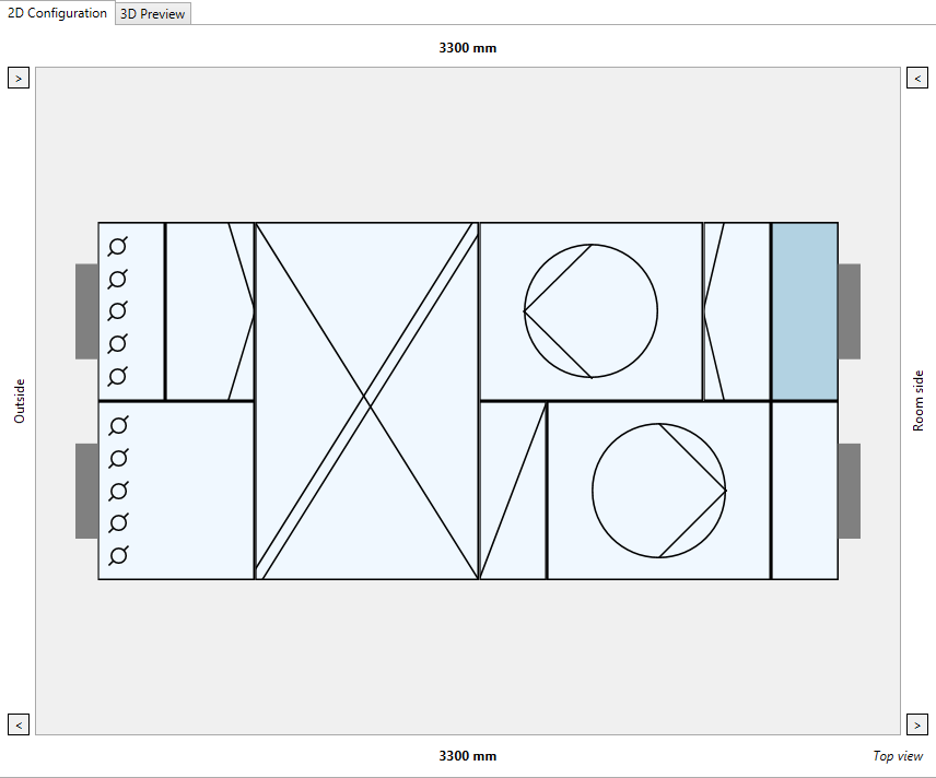
The configuration of the ventilation device is complete.
-
Click Draw and place the ventilation device in the model.
-
Press ESC twice to exit the command.
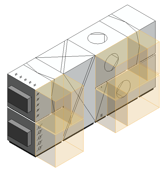
The ventilation device is inserted in the model.