-
Select the reference level in the Construction Level/ Offset (+/-) section.
-
Click Discipline.
The configurators the families of the heating discipline are displayed.
-
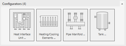
Open the Configurators section.
-
Click Pipe Manifold ....
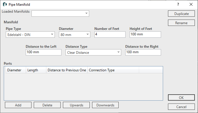
The Pipe Manifold dialog opens.
If the current project does not yet include a family for pipe manifolds, the dialog is initially empty.
-
In the Manifold group, select the pipe type for the whole manifold.
-
Enter the Diameter of the main pipe.
-
Enter number and height of manifold feet.
-
Enter the Distance to the left and the Distance to the right between the outer ports and the outer edge of the pipe manifold.
-
Select the Distance Type for all ports of the manifold.
-
In the Ports group, click Add.
A new port is created. The first row of the table represents the outer left port of the manifold.
-
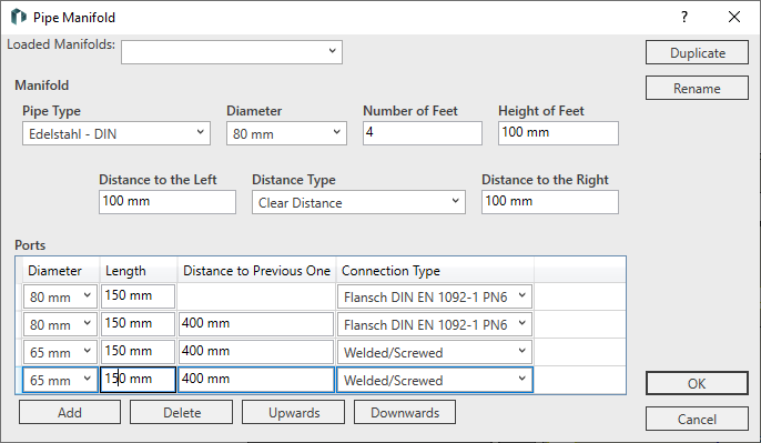
Enter the diameter, the length and the connection type of the port.
-
Add more ports and enter the Distance to previous one.
-
Click OK.
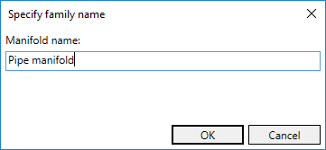
The Specify Family Name dialog opens.
-
Enter a name for family of the pipe manifold and click OK.
-
Place the pipe manifold.
-
Press ESC twice to exit the command.
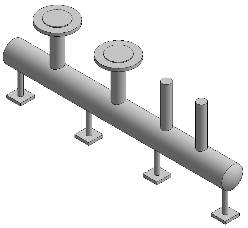
The pipe manifold is inserted in the model.