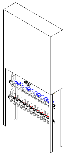
-
Select the reference level in the Construction Level/ Offset (+/-) section.
-
Select the datum level. If the datum level conforms to the reference level, select Current storey.
-
Enter an offset to the datum level.
If the component is to be located below the datum level, enter a negative offset.
-
Click Discipline.
The configurators and families of selected discipline are displayed.
-
Open the Configurators section.
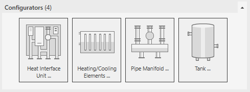
-
Click Heat Interface Unit ....
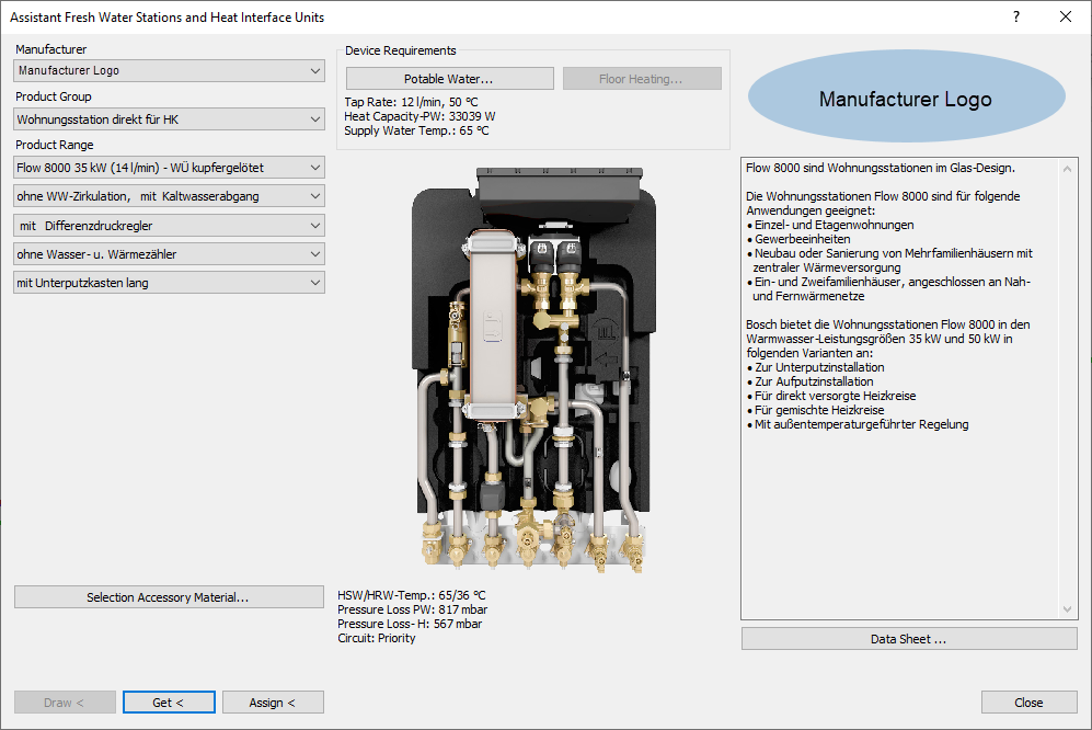
The Assistant Fresh Water and Heat Interface Units dialog opens.
-
Use the drop-down lists to select a Manufacturer, a Product Group and a model via the Product Selection.
-
If necessary, enter the nominal volume flow rates and the pressure losses of the meters.
-
Click Potable Water ....
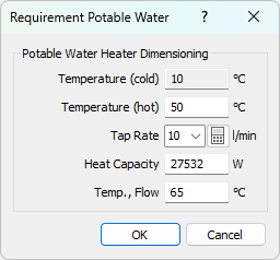
The Requirement Potable Water dialog opens.
-
Enter the requirements for potable water heating and close the dialog by OK.
-
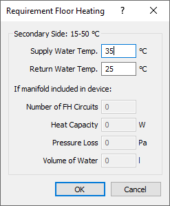
If you have selected a model including floor heating, click Floor Heating....
The Requirement Floor Heating dialog opens.
-
Enter the requirements for floor heating and close the dialog by OK.
If the requirements for potable water and heating match the selected model, the dimensioning data are displayed below the product illustration and the Draw < button is activated.
-
Click Draw <.
-
Place the heat interface unit in the model.
The heat interface unit is dimensioned and inserted in the model.