Details on Systems...
Information on the section Systems ....
You are here:
If you have created a system in 3D model planning, you can use the Create assembly plan < command to automatically generate detailed plans from the individual systems (assemblies), e.g. system 1. This requires the 3D pipes and components to be located on layers that contain a layer abbreviation for spools/sections (Partition) and systems.
Right-clicking in the list of systems opens a context menu in which you are offered various menu items for switching the element on and off.
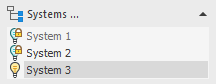
Systems ...
Opens the Systems dialog in which you create attachments.
 : The system is switched on. Thus, all layers containing the abbreviation of this system are visible.
 : The system is switched off and locked in order to prevent it from being switched back on and further application. This means: The system is deactivated and cannot be used any more. When the superior level (e.g. the trade, see layer key) is switched back on, the status of the locked system is not effected. However, switching on the layers with the Layer Properties Manager of your CAD program is possible.
To turn the system back on, click the symbol until the turned-on light bulb appears or use the Layer Properties Manager of your CAD program.
 : One or more layers belonging to the corresponding system are switched off.