Details on Edit LINEAR Connector Definitions
Information about the dialog Edit LINEAR connector definitions in the context of 3D pipe or duct construction.
You are here:
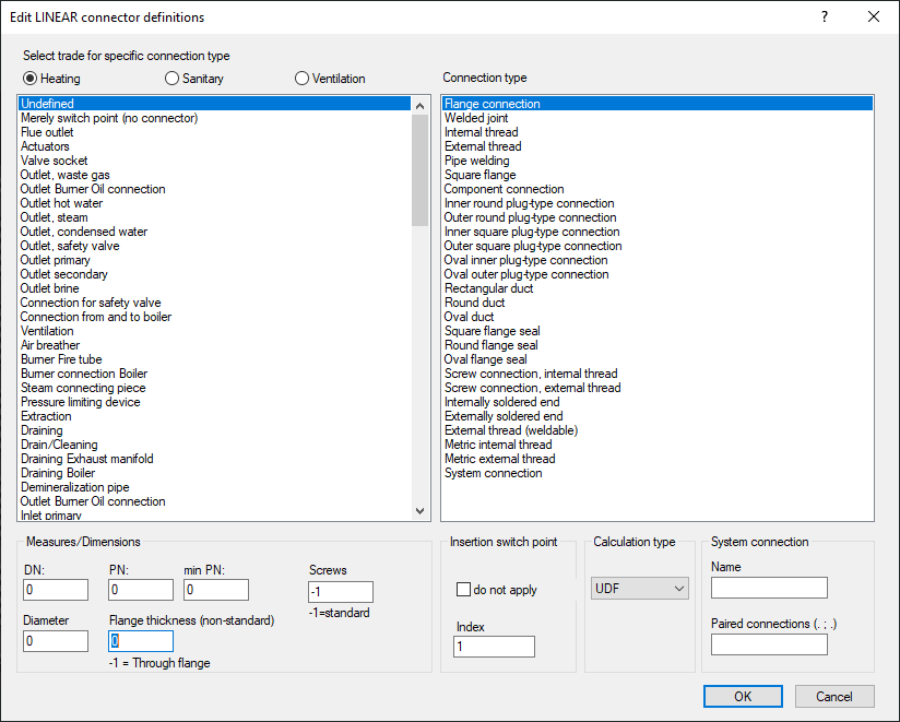
Select trade for specific connection type
Select the desired trade to display a list of suitable connection types on the left.
Connection type
Defines the type of connection to the pipe or duct network.
Measurements / Dimensions
Here you define the diameter DN and the nominal pressure PN/min PN.
When you set a Diameter, the drawing will display a corresponding graphic of the specified size around the connection. When selecting the connection type Flange connection, you can manually enter the Flange thickness (non-standard) here if it differs from the standard (standard thickness = 0). For a through flange, enter -1. If the number of holes on a flange differs from the standard (= -1), you can specify the required number of Screws here.
Insertion switch point
do not apply
Enabled: The currently selected connector will not be used as an insertion point when inserting the component.
Deactivated: The currently selected connector will be used as a possible insertion point when inserting the component and the specified index will be considered.
Index: If you have multiple connectors, you can define here in which order the currently selected connector will be selected as insertion point when inserting by right-clicking next INSertion point.
Calculation type
Depending on the selected trade, relevant media are available for selection in this drop-down list. Select UDF (= undefined) if the calculation type is not to be assigned.
System connection
| Connection geometry | Geometry dependence |
|---|---|
| RO: round | PG: Pressure Geometry = Size of the connecting pipe/duct depending on the defined pressure |
| RE: rectangular | DG: Dimension Geometry = Size of the connecting pipe/duct depending on the specified DN |