Referencing Customized Pipe, Duct, Cable Route and Conduit Systems
Shows step-by-step how to make user-defined pipe, duct, cable tray or conduit types from an Revit project template file available in the LINEAR Solutions as pipe, duct, cable tray or conduit systems.
Before you begin
You want to reference and use pipe, duct, cable route or empty conduit types that you have defined in a project or project template file in Revit in the LINEAR Solutions.
Requirements:
You have a Revit project template file or Revit project file in which the pipe types to be referenced are available as families.
Note: In the following steps, a user-defined pipe type is referenced as an example. Use the appropriate XML file to reference trunking, cable route or empty conduit types.
Procedure
- Save the Revit file containing the user-defined pipe type as a Revit project template file (file extension .rte) in the directory C:\Program Files (x86)\liNear Software\Solutions xx\CAD\RevitMain\User-Standards\User Templates\2024\ and open the file.
- Double-click on the corresponding pipe type in the Revit project browser under .
The Type properties dialog opens.

- Enter a manufacturer in the Manufacturer field if there is no entry yet.
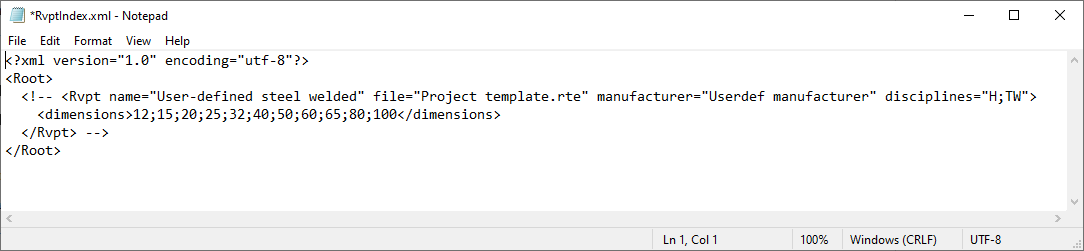
- From the file path C:\Program Files (x86)\liNear Software\Solutions xx\CAD\RevitMain\User-Standards\User Templates, open the file RvptIndex.xml (for pipe systems) in a text editor.
- Optional: Remove the commented-out lines in the XML code by removing the
<!--and-->elements. - For the
nameattribute, enter the name of the pipe system that is displayed in the Type drop-down list in the Revit Type properties dialog, e.g.name=”User-defined welded steel”. - Enter the name of the Revit project template file for the
fileattribute, e.g.file=”Project template.rte”. - For the
manufacturerattribute, enter the manufacturer name that you used in the Type properties dialog in Revit, e.g.manufacturer=”Userdef manufacturer”. - For the
disciplinesattribute, enter the abbreviations for the disciplines for which the pipe system should be available, separated by a semicolon. e.g. e.g. disciplines=”H;PW”for the disciplines heating and potable water. - Enter the nominal diameters for the pipe system in the XML node
<dimensions>separated by semicolons, e.g.<dimensions>20;25;32;65;80;100;120</dimensions>. - Optional: Create a copy of the entire XML node
Rvptand change the attribute data accordingly if you want to reference additional pipe systems. - Save and close the XML file.
Results
The next time you start Revit with the LINEAR Solutions, the pipe system will be available under in the Manufacturer and Pipe system drop-down lists.