About the Use of User-Defined Pipe and Duct Systems
Explains the concept of using custom pipe and duct systems in the LINEAR Solutions and referencing them with predefined XML files.
If you have created your own pipe or duct types in a Revit project, you can access them via the LINEAR Control Board in order to use them there to construct pipe and duct networks. To do this, you must reference the Revit project template file (file extension: .rte), in which the pipe type exists as a family, using a predefined XML file. In the XML file, you use XML attributes to specify the pipe type, the manufacturer name, the project template file and the dimensions so that the LINEAR Solutions data can be read out. In this way, you can use custom pipe and duct types in all your MEP projects without having to manually import data sets each time.
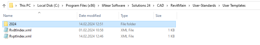
The predefined XML files are supplied and installed with the LINEAR Solutions. They are located in the directory C:\Program Files (x86)\liNear Software\Solutions xx\CAD\RevitMain\User-Standards\User Templates and can be opened and edited with all common text editors. Use the RvptIndex.xml file for referencing user-defined pipe systems and the RvdtIndex.xml file for user-defined duct systems.
For the LINEAR Solutions to access the Revit project template files, they must be stored in subfolders of the User-Templates folder according to the Revit version. For files that were created with Revit version 2024, for example, a corresponding subfolder with the name 2024 must be created, as shown below.