Details on the Calculation Dialog for Gas
Information about the dialog LINEAR Analyse Gas.
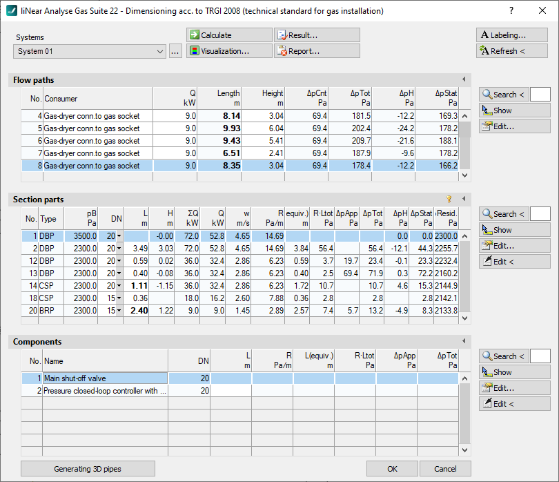
The calculation dialog shows an overview of the detected pipe network and contains all commands necessary for the calculation.
You are here:
Commands for the calculation
The commands in the upper part of the calculation dialog pertain to the entire pipe network.
| Element | Meaning |
|---|---|
| Systems | If the project contains several systems or partial networks you may determine which of the systems or partial network to display in the calculation dialog’s tables. |
| … | This button will open the technical data of the initial component. Here, you can change the system name shown in the drop-down list. |
 Calculate | Initiate the calculation of the pipe network after having made changes to see current calculation results. If you have activated the Recalculate after editing checkbox in the Settings dialog, the calculation is automatically performed again after each editing of section parts or components. |
 Visualization... | This command displays properties and calculation results of the pipe network in color in the drawing. |
 Result... | Displays additional information regarding the pipe network and an overview of the calculation results, which also are part of the printouts. |
 Report... | Displays an overview of notes and errors that occurred during calculation. The color of the button helps differentiate between notes and errors: white: No notes or errors. orange: There are notes on the calculation. red: There are errors in the calculation. Note: It is recommended to always carefully read the reports to correct errors in the drawing and ensure a proper calculation. |
 Labeling... | Label components and section parts with calculation results. |
 Refresh < | If components or section parts have already been labeled and calculation results have changed retrospectively, this button will refresh all labels with current data. |
Commands for the tables
Similar commands are available in the Flow paths, Section parts and Componentssections.
| Element | Description |
|---|---|
 Maximize list | The tables of flow paths, section parts and ventilation section parts can be enlarged over the entire calculation dialog. The other tables are hidden. |
 Minimize list | Reduces a maximized table. The other tables are displayed again. |
 Search < | The command is available in the Flow paths, Section parts and Components sections. After clicking Search < select the element in the drawing. The respective table then highlights the flow path, the section part or the component. If a certain flow path number, a section part number or a component number needs to be found, enter the number into the text field and click Search <. The respective table then highlights the flow path, the section part or the component. |
 Show | The command is available in the Flow paths, Section parts and Components sections. First, select the element from the table and click Show. The flow path, the section part or the component is shown in the drawing. |
 Edit... | The command is available in the Flow paths, Section parts and Components sections. First, select the element in the table and click Edit.... The dialog for editing components or section parts is opened. |
 edit in drawing < | The command is available in the Section part, and Components sections. After clicking edit in drawing <, select the element in the drawing. The dialog for editing components or section parts is opened. |
Table for Flow paths
This table shows the calculation data for all flow paths of the selected system. It provides an overview over all ending components of the network. If you select a flow path, the table Section parts displays all corresponding section parts. The most unfavorable flow path is highlighted in a different color. You can also select the most unfavorable flow path by pressing U.
| Column | Description |
|---|---|
| No. | Number of the flow path. |
| Consumer | Name of the consumer. The name can be modified in the table. |
| Q | Load by consumer. |
| Length | Length of the flow path. |
| Height | Height of the flow path. |
| dpCnt | Pressure loss due to meters. |
| dpTot | Sum of all individual pressure losses from pipes, built-in parts, appliances, valves. |
| dpH | Pressure loss due to changes in hydrostatic pressure (Uplift). |
| dpKin | Pressure change due to acceleration. |
| dpStat | Static pressure change measured from the flow path beginning (Pressure regulating device) to the consumer. |
Table for section parts
This table shows the calculation data for all section parts of the selected flow path. If you select a section part, the table Components displays all corresponding components.
 Unfix / fix section parts
This command allows you to fix or unfix the dimensions of all section parts. If values are displayed in bold in theDN column, the dimension of the respective section parts will not be adjusted during the calculation. This is sensible when calculating existing systems. If the dimensions of some section parts have been fixed already, you will be asked whether to fix or unfix all section parts.
| Column | Description |
|---|---|
| No. | Number of the section part. |
| Type | Section part type: DBP: Distribution pipe CSP: Consumption pipe BRP: Branch pipe SFP: Single feed pipe |
| pB | Working pressure (static pressure). |
| DN | Nominal diameter of pipes in this section part. The nominal diameter can be changed in the table. The value is then fixed and will not be adjusted by the software during calculation. Fixed values are shown in bold. |
| L | Length of section part. The length be changed in the table. The new length will be distributed among all pipes of the section parts proportionately to constructed length. All pipes affected by the change in length will be displayed bold in the tables for section parts and components. |
| H | Height of section part. |
| Sum Q | Sum- or section load. |
| Q | Peak load. |
| v | Velocity. |
| R | Pipe friction pressure loss per meter. |
| Ltot(L+L(equiv.) | Additional length of section part. |
| R*Ltot | Total pressure loss from pipe friction. |
| dpApp | Pressure loss from appliances. |
| dpTot | Sum of all individual pressure losses from pipes, built-in parts, appliances, valves. |
| dpH | Hydrostatic pressure change (Uplift). |
| dpStat | Pressure change due to acceleration. |
| dpResid | Residual pressure at the end of the section part. |
Table for components
This table shows the calculation data for all Components of the selected section part.
| Column | Description |
|---|---|
| No. | Component number. |
| Name | Name of the component. |
| DN | Dimension. |
| di1/di2 | Pipe inside diameter for pipes (ÖVGW). |
| L | Length for pipes. |
| R | R-value of pipes. |
| L(equiv.) | Length equivalent for fittings. |
| R*Ltot | Total pressure loss from pipe friction. |
| w1/w2 | Velocity relating to the pipe inside diameter d1/d2 (ÖVGW). |
| Re | Reynolds number (ÖVGW). |
| Sum zeta | Sum of resistance coefficients (ÖVGW). |
| dpP,F | Pressure loss from pipes and fittings (ÖVGW). |
| dpApp | Pressure loss from appliances. |
| dpTot | Total pressure loss. |
Generating 3D pipes
Allows the assignment of pipe materials from the 3D Piping module after the calculation of a single-line pipe network. After successful assignment, a three-dimensional pipe network is generated. Pre-assigned insulation material is considered. This process requires a license for the LINEAR 3D Design Pipe&Power module.