While architects are still developing the floor plan, MEP spaces are often based on assumptions. Future changes can quickly become very expensive. This article shows how lean, BIM-based Pipe Route Concepts solve this problem at an early stage: With only a handful of inputs, network sections are automatically dimensioned and plausibly transferred to pipe route solids and pipes. A practical example of a ventilation system for offices clearly shows how we can quickly check variants, derive cross-sections, and reliably coordinate installation spaces with the architecture. The new dimensioning offered by the Pipe Route Concept creates a continuous workflow—from room data sheet to further detailed design.
Collaboration in Early Project Phases
Early project phases are characterized by extreme variability. Room concepts are created, partially discarded, and suitable layouts for the intended use are determined. In the architectural model, a list of requirements and a plan of the relationships between spatial areas are used to create a concrete floor plan model of the planned project in several coordination steps. At the same time, significant influences from other disciplines, such as building services engineering, are still largely unknown and must be assumed. These areas often compete with the need to maximize usable space. As a result, areas for shafts, suspended ceilings, sub-distribution, and equipment rooms tend to be undersized.
The promise of BIM-based design – putting in effort up front so you can save time and money later – seems unrealistic with conventional workflows. As soon as I move beyond purely schematic concepts in my design and start working with concrete distribution systems and the transfer of the individual media, even seemingly harmless change requests can result in costs comparable to those of the initial construction of the areas affected. Due to the interdependencies, a design freeze at which the structure can be accepted as the final construction framework for the technical equipment is rather an exception than a rule. A high level of cooperation and project experience on the part of everyone involved is required in order to avoid significant overhead for redesign.
Lean pipe route models offer a way out of the nightmare of redesign. These models are developed at a significantly lower level of detail but offer flexibility in terms of adjustments at the same time. The development of such methodologies and the necessary tools have been underway for several years. In this article, we would like to present a decisive stage of development which allows the structuring influence of the MEP design to be taken into account at a very early stage.
What has happened so far?
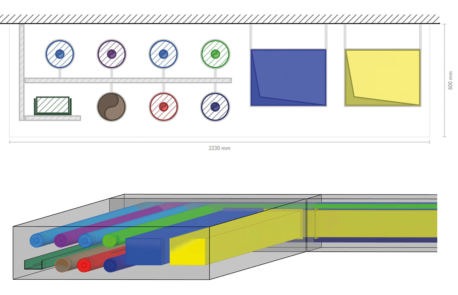
Taking early MEP design to the next level using BIM methodologies requires new models that generate high informative value with as few degrees of freedom as possible and allow existing data to be transferred to further detailing. We already presented a proposal for this type of streamlined models in our magazine LINEAR aktuell 2/2020 with the introduction of the Pipe Route Concepts in our LINEAR Desktop. The key innovation here was that, for the first time, entire bundles of pipes and ducts could be combined as simple line-based structures with a two-dimensional cross-section plan in order to dimension obstructions. If desired, space requirements for suspensions or reserved spaces could also be planned here. This approach not only made it possible to discuss space requirements for MEP systems at an early stage. As a pleasant side effect, the pipe route modeling could already be converted into actual pipes, including insulation (see Figure 1).
In a follow-up article in the LINEAR aktuell 2/2022, we outlined ideas based on this that allow us to move from the mere construction of such multi-system pipe routes to largely automated and model-based dimensioning, which greatly simplifies the design of comprehensive Pipe Route Concepts. Now we want to take these ideas off the drawing board and put them into practice. Before we go into detail, let's briefly review the main ideas.
Anyone who uses LINEAR is probably familiar with our network calculations. We therefore base our method for pipe route dimensioning on an analogy in which we treat certain technical areas (e.g., for equipment rooms or roof top units) as generators and areas of use (rooms or broader areas of the same use) as consumers that communicate with each other via shafts and pipe routes. In addition to the placement of the pipe route solids and the specification of certain boundary conditions (e.g., building type, velocity limits), all that remains is to define transfer points and coverage for the individual systems. Based on this information, a system topology can be derived from a simple Pipe Route Concept and—taking into account technical constraints (e.g., simultaneities)—correctly dimensioned pipes can be automatically assigned to each pipe route segment. The key point is that this can be done at any stage of the preliminary design process and does not require any data that we do not already have or cannot easily enter. Since we consider our rooms to be central modeling elements, interesting synergy effects with an approach based on room data sheets start to unfold.
Network Structure
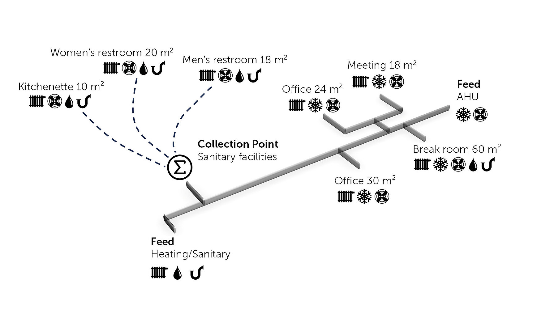
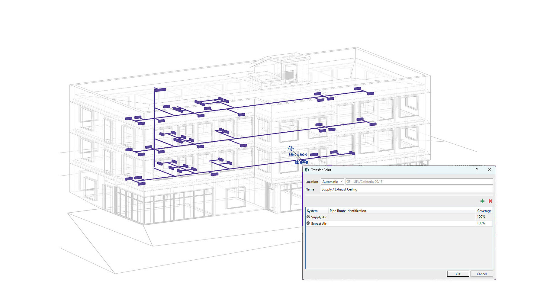
The basic network structure in Revit is hardly any different from early ventilation design with partial network start and end components. The corresponding routes for the supply pipes are modeled using suitable pipe route model classes. Here, a decision must be made as to where riser zones are located and whether horizontal pipe routes should be placed in floor or ceiling. Corresponding transfer and collection points model the supply of specific rooms, which at this stage can still be grouped into broader categories. A simplified representation of a pipe route system is shown in Figure 2.
For the actual modelling in Autodesk Revit, LINEAR Solutions offers ready-made families for designing construction space for pipe routes and for the required feeds and transfer points. However, using an appropriate classification also allows the use of your own families.
Method for Dimensioning
A pipe route can be defined sufficiently well for an early model phase using a given pipe route network and information relevant to supply at the end points (coverage ratios, differential temperature, etc.). This means that for each trade, corresponding networks can be derived based solely on connectivity, and totals for the required flows in the individual network sections can be calculated. In the case of sanitary networks, standard simultaneity approaches are also taken into account when determining peak flows.
For clarification, let's take a look at the sanitary network implicitly contained in Figure 2. If I ignore all network sections that do not need a potable water supply, the network structure can be simplified considerably, as shown in Figure 3.
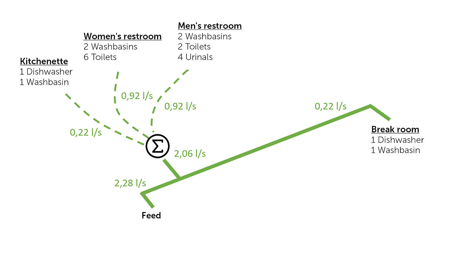
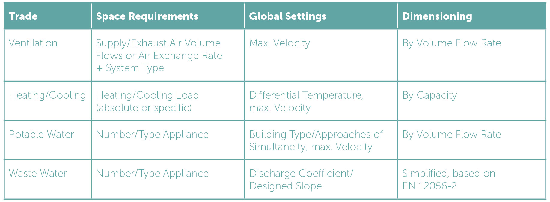
At the network ends, numerical data can now be used to specify the appliances to be considered in the rooms, thereby determining the required total flow at the network ends. Combining this information with a simultaneity approach for the respective building type, peak flows can be easily determined. By combining this with a maximum velocity, nominal diameters for the pipe sections can also be easily determined.
Heating and cooling systems can be treated in the same way, whereby it is not flow rates but outputs that are cumulated. These can be converted to volume flows by specifying a differential temperature in the system and to nominal diameters at limited velocity. The space-related requirements are typically determined here by specifying area-related loads. If a detailed heating/cooling load is already available, the results can of course be used. The air volumes determined in a ventilation concept can also be applied directly to ventilation dimensioning. Alternatively, if a ventilation concept is not yet available, the missing information for initial dimensioning can be derived from the system type in the room (supply/exhaust air) and a draft air exchange rate from the room volume.
Practical Example
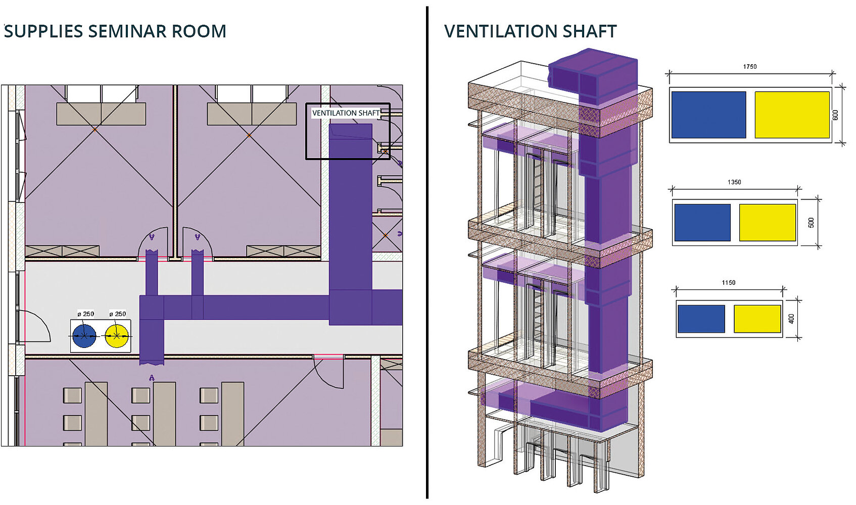
To illustrate the workflow in the LINEAR Solutions for Revit, let's take a look at a ventilation system in an office building. The system consists of a rooftop unit, which feeds into the ventilation network. The air is extracted via 54 transfer points (one per ventilated room), with each transfer point specifying whether supply air and/or exhaust air is to be connected.
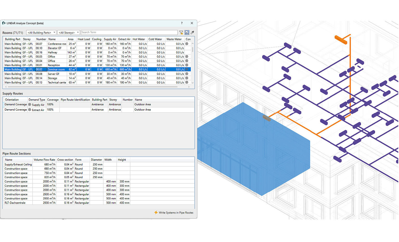
With these simple preparatory steps, it is possible to obtain a fully dimensioned pipe route model. The plausibility of the calculated dimensions can be checked using the built-in network visualization. The dimensioned systems can then be automatically written to the modeled pipe route elements.
After enriching the pipe routes, parametric layouts can be defined for the cross sections. In this example, a uniform cross-section (supply air next to exhaust air) was applied while retaining the individually determined dimensions for the entire building. By combining the dimensions with cross-section plans, the pipe route solids can now be redimensioned and exported as obstructions, e.g., via the IFC path, for those responsible for the building. However, LINEAR tools can also be used to create informative documentation of the most important project stages. At the start of the next project phase, the pipe function for generating pipes and ducts can be used to create an initial pipe network for further detailing.
Conclusion and Outlook
The LINEAR Pipe Route Concept has been significantly enhanced with the new dimensioning assistant. With simple workflows, it is possible to dimension even large networks with multiple systems based on space requirements and quickly examine variants. The tools shown have been available to all customers since version 26.0 as a beta version at no additional license cost. Significant improvements in redimensioning, i.e., the automatic resizing of pipe route solids and subsequent pipe creation, will be implemented before the final release. We are convinced that this development can form an important building block for coordinating MEP construction spaces in early project phases in the future. Get started now with this feature and get in touch with us. Together with you, we want to take MEP design to the next level.