Creating Curve Data for Pressure Losses in Ventilation Components
Shows step-by-step how to create custom data sets for to ventilation components.
Before you begin
You want to create manufacturer-specific data sets for ventilation components with corresponding pressure loss data to assign them to ventilation components in your model.
Requirement:
You have manufacturer-related component data for to ventilation components.
Navigate to:
Procedure
- Open the context menu in the Manufacturer row via the function button
 and select Create entry.
 The Create manufacturer dialog opens.
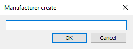
- Enter a manufacturer name and confirm the entries with OK.
- In the Model series row, open the context menu via the function button and select Create entry.
The Create model series dialog opens.
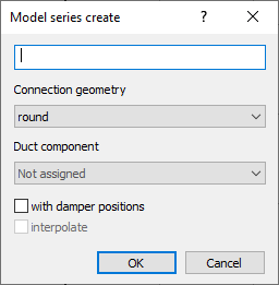
- Enter a name for the model series and select a Connection geometry from the drop-down list.
- In the drop-down list Duct component, select a component type.
- Optional: Select the option with damper positions, if necessary combined with interpolate.
- In the Nominal diameter row, open the context menu via the function button and select Create entry.
The Create nominal diameter dialog opens.
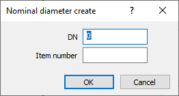
- Depending on the selected connection geometry, enter a nominal diameter (round pipe) or two values for the side lengths a and b (rectangular duct).
- Enter an item number and confirm the entries with OK.
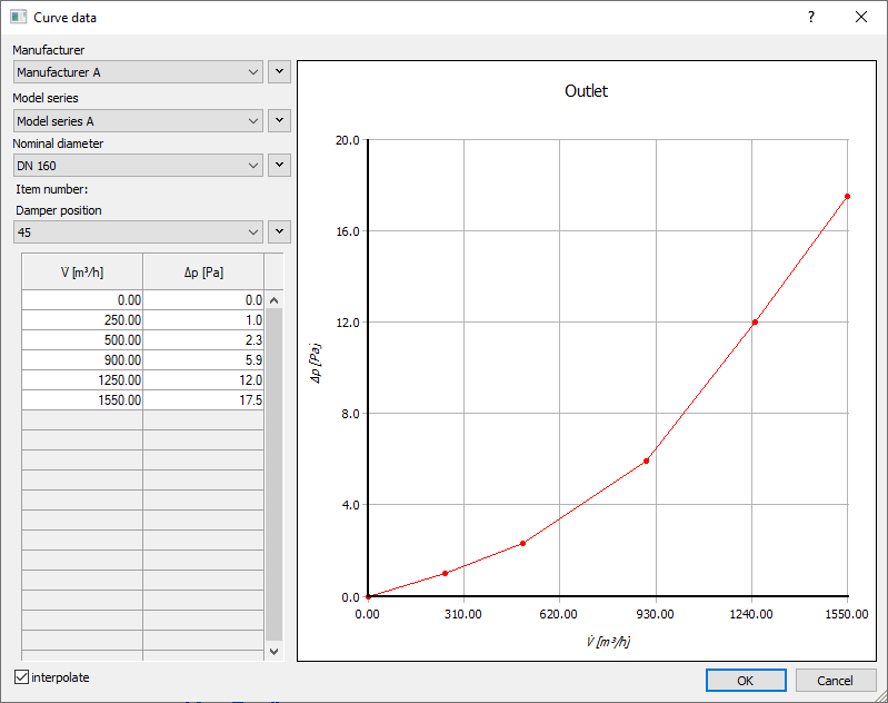
- Optional: If you have previously selected the option with damper positions, open the context menu in the row Damper position via the function button and select Create entry. Note: You can define several damper positions for each article and then specify them with individual volume flow and pressure loss data.
- Enter the data for the volume flow V and the pressure loss dp in the table. The entered data is displayed as a pressure loss curve in the curve diagram.
Results
You have created a component dataset for a ventilation component with curve data. The data can now be assigned to ventilation components in the Technical data dialog and is available in the Duct components dialog.