Details on Configuration - 3D Air Duct Construction
Information about the 3D Air duct construction tab in the LINEARconfiguration.
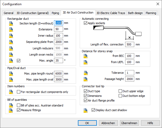
The specific presettings for the LINEAR 3D air duct construction are made here.
You are here:

Rectangular duct
Section lengths
Specifies the section length for ducts in mm. If you would like to work without section lengths, enter 0 mm as the section length.
Extensions
Specifies the extension for transitions in mm.
Inner radius
Specifies the inner radius for bends in mm.
Separating plate from
Specifies the duct size from which a separating plate will be inserted.
For the parameter Separating plate from, enter the value 0 so that separating plates do not appear in the parts list.
Length reducers
Specifies the value suggested in the Length field in the dialog box for transitions.
Length swan necks
Specifies the value suggested in the Length field in the dialog box for swan necks.
Max. angle
Specifies the maximum angle dimension for air ducts. If you activate the maximum angle by setting the check mark, the length for the transitions and swan necks in the dialog boxes is automatically determined optimally in terms of flow.
If you deactivate the maximum angle by removing the check mark, the length for transitions and swan necks will be suggested with the lengths you have specified for the 3D air duct construction.
Pipe/Oval duct
Specifies the maximum pipe lengths for round pipe and oval duct. If you enter a maximum pipe length of 3000 mm here, round and oval ducts will be drawn in sections of 3000 mm each in your drawing and taken into account for the parts list. If you would like to work without section lengths, enter 0 mm.
Item numbers
If activated For rectangular duct components only, item numbers are assigned for rectangular ducts.
Bill of quantities
Specifies whether the bill of quantities should be based on the Austrian standard and whether fittings should be measured.
Automatic connecting
Specifies whether sockets should be installed during automatic connecting and how long the connection of the flexible connection should be. The setting 0 in the Length of flexible connection means that no flexible connection is used.
Distance for storey snap
Specifies the distances for the storey snap. When working with a storey table, the reference edges upper edge floor (UEFL) and bottom edge ceiling (BEC) are automatically snapped with the set value when drawing vertically with the Ctrl key pressed.
Tolerance
Determines the size of the deviation of two duct pieces that are still connected without automatic insertion of a bend when using the Connect command. The graphic display of this duct section is not perfect then, but the bill of quantities is correct.
Passage height
Specifies the height that should be kept clear during the height distance at passage height.
Connector tool tip
Specifies which information is displayed when connecting to a component.
Duct cast shadow
Specifies whether shadows are created for the ducts in the drawing.