Details on Configuration - Pipe Run Scheme
Information about the section Pipe run scheme in the Configuration of LINEAR Building.
These functions are only available in conjunction with AutoCAD and only come into effect if you draw or label radiators or cooling convectors using an AutoCAD version without LINEAR - CAD. If you are working with LINEAR CAD, the settings there have priority in the Configuration on the Planning tab.
You are here:
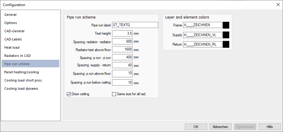
Pipe run scheme
Pipe run label
Specifies the label block used to label pipe runs. The specification refers to the folder ...User-Standards\Labels.
Text height
Sets the height of the text used to label an object.
Spacing radiator - radiator
Specifies the distance between the radiators or cooling convectors in the generated pipe run scheme .
Radiator text above floor
Specifies the height above the floor where the text of the radiator or cooling convector is inserted.
Spacing: Pipe run - pipe run, supply water - return water, pipe run above floor, pipe run below celling
Define the distances used for the generation of the pipe run scheme. If necessary, vary the values to avoid overlapping labels.
Draw celling
Activated: Ceilings are drawn in the generated pipe run scheme.
Deactivated: Ceilings are not drawn in the pipe run scheme.
Same size for all radiators
Activated: All radiators and cooling convectors are drawn in the same size.
Deactivated: The actual dimensions of the radiators and cooling convectors are taken into account in the pipe run scheme.
Layer and element colors
Frame, Supply, Return
Specifies the layers on which the frames of the label texts, the label texts themselves, the radiator and cooling convector blocks and the supply and return water pipes are drawn. Clicking the color fields opens the dialog Choose Color, where you specify the colors used.