Details on Creating a Panel Heating/Cooling
Information on creating a panel heating/cooling in 2D and 3D Floor Planning.
With the commands of the Panel heating/cooling assistant, you can provide floor, ceiling and wall surfaces with panel heating/cooling elements. In addition, you can draw manifolds and feed pipes. Several manufacturers and systems are available, depending on your program version and the licenses. Which assistants are present on your computer depends on the program version and licensing. Therefore, the commands documented here may not be available to you.
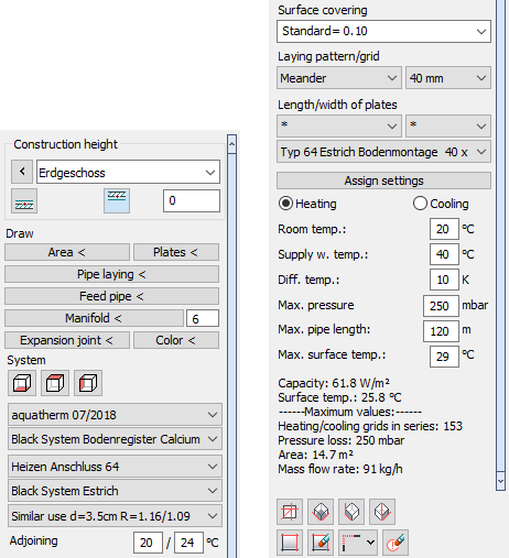
Draw
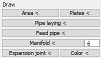
In the Draw section you find all the commands you need to draw in panel heating/cooling systems. For a detailed description of each button, see the help page for the Draw section.
System
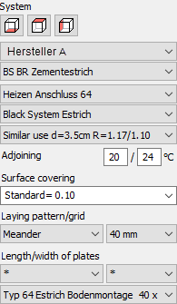
Position of system
Use the buttons for floor/ceiling/wall  to define the position of the panel heating/cooling element in the room.
Not every manufacturer offers ceiling and wall systems.
Manufacturer, System group, System, Pipe
Specifies the desired manufacturer, the manufacturer's system group, the system of the system group and the pipe used. Availability of manufacturers depends on your program version and installed as well as licensed product datasets.
Insulation variant
Determines the insulation type to be used. The choice of the insulation variant should depend on the conditions to which the room with panel heating/cooling component is adjacent. The variants offered are manufacturer and system dependent.
Adjoining temp.
Sets the minimum and maximum temperature adjacent to the room.
Surface covering
Specifies the surface covering to be used with the associated R-value (Heat conduct resistance) the surface material. The R-value of 0.10 m²K/W is suggested as the standard value according to DIN.
Laying pattern
Defines the laying pattern of the panel heating/cooling. Depending on the system you have the choice between Spiral Meander, Double meander, Blind area (without pipes) and Varying.
Grid
Defines the laying spacing between the pipes. Which distances are available depends on the system.
Length/width of plates
Allows you to specify the dimensions of the plates to be used in systems with register plates and to filter by certain plate dimensions. For other systems, this area is disabled. When filtering by plate lengths and widths, use the * entry to display all available plate dimensions in the drop-down list below. After defining the plate dimensions, the command Plates < in the Draw area is activated. If different installation variants are available for the panel systems, they can be selected here.
Assign setting
Allows you to apply changes to the manufacturer, system, installation type, laying spacing, etc. directly to circuits or installation areas that have already been drawn and marked, thus eliminating the need to redraw them. For manifolds, you can adjust the number of circuits that can be connected.
Dimensioning help
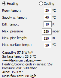
After selecting a system, you can enter the following key data for the design of the Panel heating/cooling system in the design aid area: Heating or cooling, room temperature, supply water temperature, differential temperature, maximum pressure loss, maximum pipe length and maximum surface temperature. Then the following determined values are output in the information area: area-related capacity, surface temperature, maximum pipe length, maximum pressure loss, maximum circuit area and the mass flow rate.