Create Assembly Plans with Systems and Spools
Shows step-by-step how to create assembly plans from drawings that are divided into systems and/or spools.
Before you begin
You want to create assembly plans from a drawing that is divided into systems and/or spools.
Requirement:
The components in the drawing are divided into systems (assemblies) and/or spools.
Navigate to:
Applies to Heating, Potable water, Waste water, Ventilation, Panel heating/cooling, Cooling, Gas, Fire protection, Electrical, Mounting planning.
Procedure
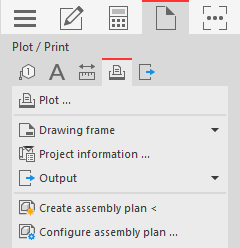
- Click on Create assembly plan <. The following prompt appears in the command line: Show component from system/spool/section.
- Select a component in the drawing that belongs to the system (assembly) or spool for which you want to create an assembly plan. The command line displays the prompt: Show horizontal main view direction.
- Use the mouse to point to the main horizontal view direction and click to confirm in order to define the horizontal position for displaying the components in the assembly plan. Note: If you wish, activate the Orthomode (F8) to make the input more precise.The following prompt appears in the command line: Show vertical main view direction.
- Use the mouse to point to the main vertical view direction and click to confirm. The Assembly layout settings dialog opens.
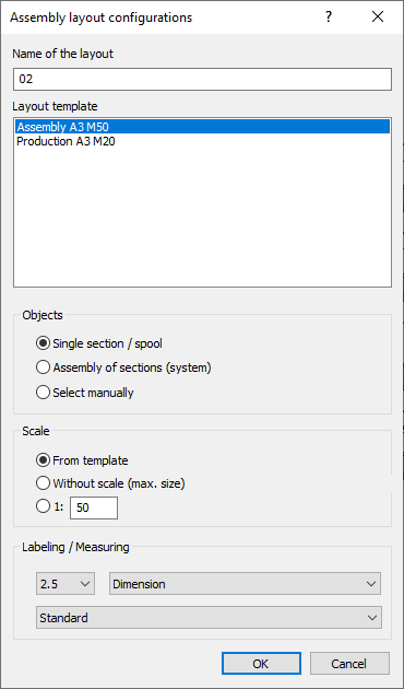
- Enter the name for the layout tab on which the assembly plan is displayed.
- In the Layout template area, select the template to be used for creating the assembly plan.
- In the Object layer area, specify whether the assembly plan shows all components of the corresponding spool (individual section / spool) or the corresponding system (entire assembly / system).
- In the Scale area, specify whether the scale of the layout template, the largest possible complete display in the view windows or a manually entered scale is to be used.
- In the Labeling / Dimensioning area, use the first drop-down list to specify the font size to be used.
- Use the second drop-down list to specify which additional information is to be output with the label.
- Use the third drop-down list to specify the dimensioning style to be used.
- Click OK. The assembly plan is created and opened as a separate layout.
Results
You have created an assembly plan from a drawing that is divided into systems and/or spools.