Details on Drawing a Panel Heating/Cooling
Information on drawing a panel heating/cooling in 2D and 3D Floor Planning.
You are here:
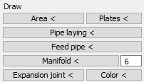
Area <
Before you draw slabs or heating/cooling circuits, you must first define a laying area. Click the Area < button and define the corner points of the laying area in the drawing. In case of rectangular rooms, you can click the two opposite points to define the laying area. If room contours already exist, laying areas in the rooms can be drawn automatically using the Room selection option. To do this, open the context menu with the right mouse button after activating the Area < command and click on Room selection. You can then define laying areas by selecting room contours.
| Command | Description |
|---|---|
| End | Ends the input command for the laying area at the last selected point and closes the area by means of connection to the first point, if the first and the last point are not identical. |
| Back | Undoes the last drawing step. |
Editing laying areas
If you select a laying area, a heating circuit or a supply line, you can open the context menu with the extended editing options by clicking on the bar buttons ![]() . Here you will find the familiar editing functions.
. Here you will find the familiar editing functions.

| Command | Description |
|---|---|
| Add/Remove contour points | Allows you to add more contour points to the laying areas and delete existing contour points. By adding contour points in combination with the grip editing function of the contour points, you can customize the laying area. Tip: You can subsequently edit the contour points of laying areas with circuits. The pipe routing adjusts automatically during the process. |
| Add/Remove open areas | Allows you to define areas within the laying areas that should be kept free from pipe laying and to delete such areas. In order for the open areas to be taken into account when drawing the heating circuits, the circuits must be (re)drawn. |
| Add/Remove joints | Allows you to define joints within laying areas, to which the laying of the circuit is oriented. Joints divide the laying area into partial areas, in each of which a separate circuit is inserted when drawing in. |
Plates <
This command allows you to design laying areas with plate systems. In some systems, after selecting the laying area, you can choose the desired way of laying the plates in the context menu. It is possible to insert the plates individually or let the program do the layout automatically. You can decide whether you want to lay whole plates or cuts and whether you want to start with or without offsets. After selecting the type of laying, you specify the length of the area to be laid by means of the start and end points. When the laying side is to be determined, indicate the width of the area to be covered with plates by placing a dot inside the laying area. Then enter the number of rows of plates or confirm that the width shown should correspond to the area to be laid by pressing Enter. Depending on the system, the plate dimensions must be defined to activate the command.
Pipe laying <
With this command you draw heating and cooling circuits in laying areas. After selecting the laying area, you have the option to have the total area installed automatically by showing the Start side of the heating or cooling circuit orientation (mouse click in the installation area) or to determine the areas of the individual heating circuits yourself by selecting the Free option. You can reach the options via the context menu or by entering F (free) in the command line. After defining the start side, you can select the desired number of circuits in the context menu.
Editing pipe laying
If you select a laying area, a heating circuit or a supply line, you can open the context menu with the extended editing options by clicking on the bar buttons ![]() . Here you will find the familiar editing functions.
. Here you will find the familiar editing functions.

| Command | Description |
|---|---|
| Switch sense of rotation of laying | Allows you to change the direction of pipe laying when using the spiral laying method. When changing the direction of rotation, a loop may be generated at the starting point. The supply and return connections retain their positions. Original setting  Changed direction of rotation  |
| Laying angle | Allows you to adjust the laying angle when laying meander. You can select 0°, 45°, 90°,135°, 180°, 225°, 270° and 315°. The supply and return connections retain their positions. Original setting  Laying angle 90°  |
| Swap supply and return pipe | Allows you to swap the supply and return connections of circuits. The connections retain their position. |
| Delete or re-calculate laying | Allows you to remove the inner laying of a circuit. The circuit is not deleted entirely. With Recalculate laying, the circuit is redrawn again. Laying deleted  |
| Add/Remove laying points | Adding and removing pipe laying points allows you to manually and individually adjust the circuit laying. Use the Add laying point command to draw in additional parts of the pipe layout that are automatically connected to the existing circuit. It is also possible to delete the pipe laying beforehand and redraw it completely manually. For this purpose, an auxiliary grid with half the laying spacing is displayed and the cursor is equipped with the corresponding snap. For the Remove laying points command, you select two auxiliary points of the pipeline between which the pipe laying is to be removed. After removal, the pipe between the two points is automatically closed again. By selecting the command the object snap for endpoints is automatically activated. Selection of pipe support points  Result after removal  |
| Add/Remove contour points | Adding and removing contour points allows you to edit heating circuit areas subsequently, for example, to open a part of the circular surface afterwards. The pipe routing adjusts automatically during the process. |
| Balance/adjust circuit lengths | Allows you to bring already drawn feed pipes and circuit zones to the same pipe length even if you have different laying spacings. If manual readjustments are necessary in order to compensate for gaps in relocations that have been created during the balancing process, use the option Consider grid spacing for circle limits and make the manual corrections of the edges, if necessary, to obtain adjusted circle lengths (see description Consider grid spacing for circle limits). |
| Distribute circuits over width | Allows you to evenly distribute already drawn feed pipes and circuit zones across the entire width of a room. |
| Global settings | Allows you to specify various global settings regarding the graphical display and the use of drawing aids. |
| Command | Description |
|---|---|
| Display detailed pipe laying | Activated: Heating and cooling circuits are displayed in detail and you can, for example, directly see the installation patterns of the circuits. This setting affects all circuits in the drawing.  Deactivated: Heating and cooling circuits are displayed in a reduced way and the internal routing is not directly visible. The reduced graphical representation improves performance. This setting affects all circuits in the drawing.  |
| Display pipe laying with color transition | Activated: Heating and cooling circuits are displayed with color gradient from red to violet to blue. This setting affects all circuits in the drawing.  Deactivated: Heating and cooling circuits are displayed without color gradient. This setting affects all circuits in the drawing.  |
| Display connector arrows | Activated: Heating and cooling circuits are displayed with connector arrows. This setting affects all circuits in the drawing.  Deactivated: Heating and cooling circuits are displayed without connector arrows. This setting affects all circuits in the drawing. 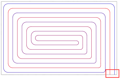 |
| Use alternative layout routines | When combining certain room situations with certain layout settings, the graphical representation of pipe laying circles may not be displayed correctly. In such cases, activate the alternative layout routine to correct the graphical representation. This setting affects only the layout of the pipe laying of the circle in whose context menu the setting was activated. |
| Show grips on pipes | If necessary, the drawn pipe routing of the heating or cooling circuits can be adjusted manually. For this purpose, it is usually useful to make the required grips (grips: small yellow squares) of the pipe visible. With the help of the grips, you can then customize the pipe guide.  |
| Set Max. wall distance (...mm) | Allows you to adjust the maximum wall distance (distance from the pipe to the circuit area boundary). The default setting is half laying spacing. If you want a different maximum wall distance, enter the desired value in mm in the command line after clicking the command. Note: The maximum wall distance must not be greater than half of laying spacing. |
| Consider grid spacing for circle limits | When balancing the lengths of the circuits, it is possible that due to the size of the rooms and the selected laying spacing, gaps may occur in the laying because the remaining areas are no longer large enough to accommodate another loop in the laying area. These gaps usually occur in the middle of the room and are particularly visible in the meander laying pattern. 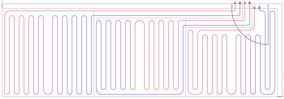 You can include the laying spacings of the circuit zones when determining the circuit zone sizes and minimize these gaps by activating the option Consider grid spacing for circuit limits before matching the circuit lengths. This means that the grid spacing is taken into account when matching the circuit lengths, so that as few gaps as possible are created. If you now adjust the circuit lengths, the pipe lengths of the circuits are adjusted taking into account the laying spacing. The last circuit covers the remaining area and does not take into account the laying spacing. Under certain circumstances, this may result in a gap in the laying pattern at the last circuit, as the remaining area is no longer large enough to accommodate another loop in the laying area. 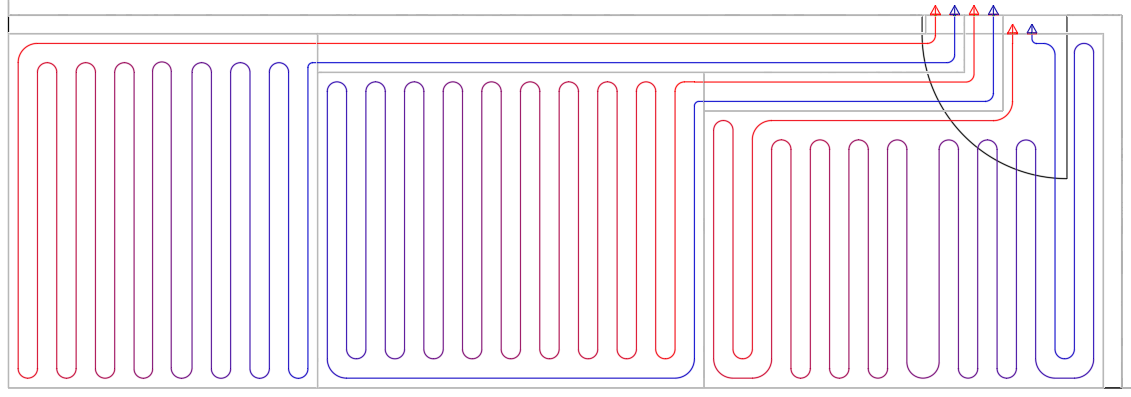 You can adjust this type of gap manually via Grip Editing. To do this, click on the corresponding gripping point and move the circuit limit while holding down the mouse button. If the option Consider grid spacing for circuit limits is activated, the circuit boundary only moves on the grid.  With manual gap of the last circuit closed by moving the circuit limit a little more into the room space.  Using the Consider grid spacing for circuit limits option may result in zones not optimally covering the entire room area and in circles not being optimally matched to their lengths, since the possible steps in grip editing are coarser. By holding down the Ctrl key, you can temporarily deactivate the currently active mode during Grip Editing. If the option is enabled, deactivate it by holding down the Ctrl key. If the option is disabled, activate it by holding down the Ctrl key. |
Feed pipe <
This command allows you to draw feed pipes to connect heating or cooling circuits to manifolds.
| Command | Description |
|---|---|
| End | Stops drawing feed pipes at the corresponding point. |
| End (+ manifold connection) | Stops drawing at the last selected point, automatically generates a pipe extension to the manifold and connects the feed pipe to a previously defined manifold connector, if it was defined. Use this command instead of the Connect automatically command for more complex connection situations, e.g. where pipes run to the manifold inside a wall, feed pipes arrive at the side of the manifold or ceiling systems are to be connected. When connecting, the distance still required for the connection of further supply pipes under the manifold is automatically taken into account. The required distance depends on the choice of the manifold connector. If, for example, you connect pipes coming from the right to the left manifold connectors, enough space is left under the manifold for establishing the connections on the right side.  The additional pipe lengths resulting from the connection are taken into account in the capacity and pressure loss calculation. Note: The power output is provided through the component on the supply pipe. If this command is used excessively (very long manifold connections), this can lead to problems with the surface temperature of the component through which the capacity output takes place. |
| Back | Undoes the last drawing step. |
| Run along adjacent pipe | The function automatically creates a feed pipe along already drawn feed pipes and, if necessary, also ties them to the manifold. Changing laying spacings of the neighboring supply pipe are automatically applied. |
| Select manifold | Allows to select another manifold by clicking in the drawing. When drawing feed pipes, the manifold no longer needs to be explicitly selected. As soon as you start drawing the feed pipe, the nearest manifold is automatically used. If this is not the desired manifold, you can use this command to select another manifold. |
| Automatic connecting | Automatically connects the feed pipe to the manifold. |
| Connect manually | Enables manual connection of feed pipes to manifolds. This command is suitable for drawing the feed pipe in 3D if you do not want the feed pipe to be routed in the way it is created during automatic connection. |
| Change manifold port | Allows you to select a different manifold port. When drawing the feed pipe, a yellow line indicates the connection to the nearest manifold port. If this is not the desired manifold port, you can use this command to select another port. |
| Lead outside left/left/center/right/outside right | Enables the guide to be changed while drawing feed pipes, thus making it possible to follow the course of a wall at a certain distance, for example, with the help of object snap. |
| Change laying spacing | Allows to change the laying spacing between supply and return pipe while drawing the supply pipe. Select Entry... to enter the desired laying spacing in cm via the command line or Manifold port to confirm the distance between the two selected manifold ports as the laying distance. |
Manifold <
This command allows you to draw in manifolds. In the field to the right of the button, set the number of heating or cooling circuits to be connected before activating the command to determine the number of manifold ports. Before you place the manifold, various options for placement are available in the context menu.
Expansion joint <
With this command you can define separating joints within a laying area. The joints serve as orientation for the laying of the circuits. Joints divide the laying area into partial areas, in each of which a separate circuit is inserted when drawing in.
Color <
This command allows you to colorize circuits including their feed pipes in different colors. The number of colors to be used (max. 8) and the colors themselves can be customized by the user by making entries in the command line. The default order of colors when coloring is Red, Green, Magenta, Blue.