Details on Connecting Components in the Heating and Cooling Disciplines
Information about the Connect components section in the Heating discipline and the Cooling discipline.
You are here:
Applies to: Heating, Cooling.
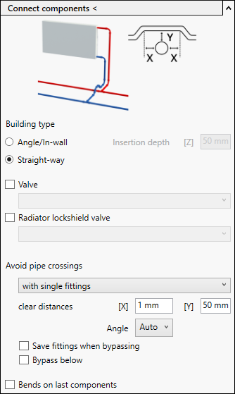
Connect components <
Automatically connects components to the selected supply and return water pipes.
Type
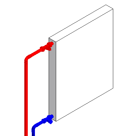
Angle/In-wall:
With this connection variant, the pipes are led into the wall. In order for the program to determine where the walls are located, MEP spaces are used. With the Insertion depth [Z] you define how deep the pipes are inserted into the wall.
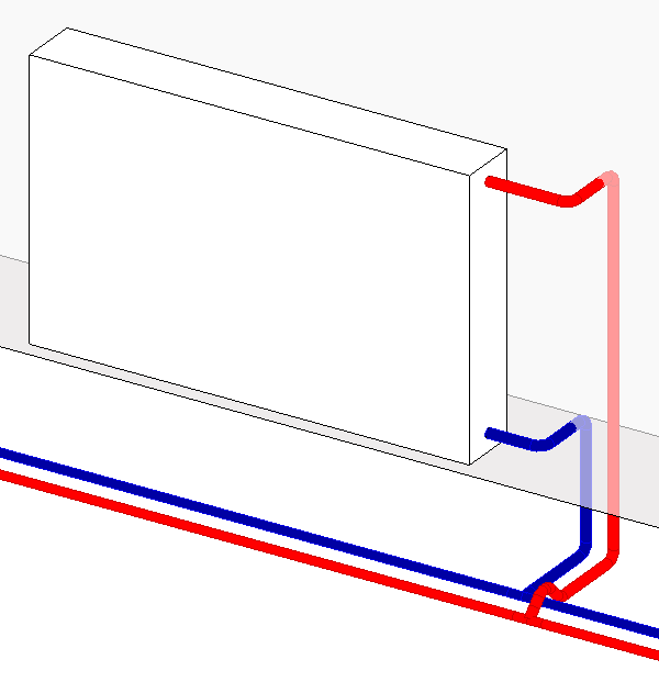
Straight-way:
With this type of connection, the pipes are led directly down from the radiator.
Angle/In-wall | Straight-way: |
|---|---|
 The pipes are first led horizontally from the component into the wall. The insertion depth into the wall can be changed. The pipes are led vertically downwards to the height of the main pipe and then connected horizontally. The Insertion depth [Z] is measured from the wall to the outer edge of the vertical pipe. 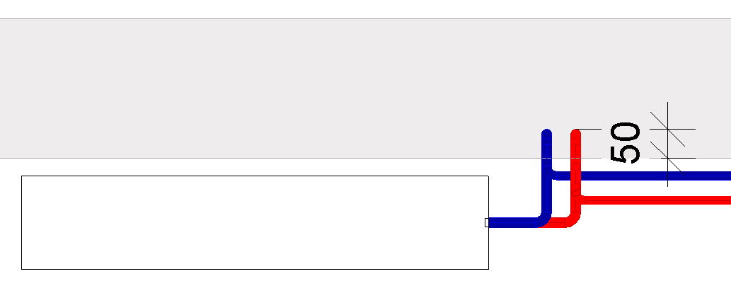 | 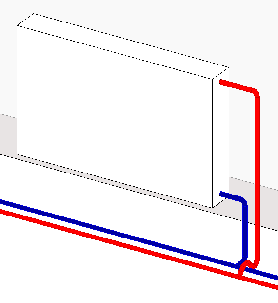 The pipes are led directly down from the component and then connected horizontally. |
Valve, Radiator lockshield valve
For the connection of the radiators, you can also determine whether valves and/or radiator lockshield valves are to be installed. To do this, activate the corresponding checkboxes. Precondition for the availability of these options is that usable pipe accessory families are loaded in the project. You can load pipe accessory families either by searching for the desired component in the Library tab and once clicking it or by loading the desired component from LINEAR CAD Browser into the project.
Depending on whether you have activated or deactivated the Angel/In-wall or Straight-wayoption, the selection of valves is filtered for suitable components. If the option Angle/In-wall is activated for the version, only matching angle valves are displayed. If the option Straight-way is activated, only matching straight-way valve are displayed.
| Straight-way, valve and radiator lockshield valves activated | Straight-way activated - Valve and radiator lockshield valve deactivated |
|---|---|
 The Straight-way version was set together with the Valve and Radiator lockshield valve options to connect the radiator. According to the settings, a thermostatic valve was installed in the supply water and a radiator lockshield valve in the return water. | 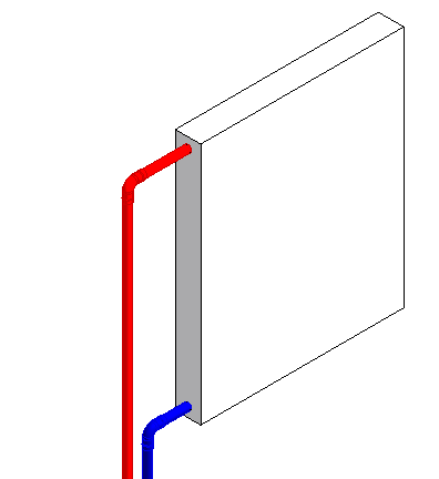 The Straight-way version was set without the options of Valve and Radiator lockshield valve to connect the radiator. According to the settings, no pipe accessories were installed either in the supply nor in the return. |
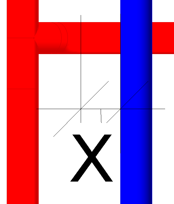
Avoid pipe crossings
In the drop-down list, the LINEAR cross over, standard family is available for selection by default, which contains matching cross-overs. Furthermore, the function lists those families loaded in the project that could also have cross overs. If LINEAR cross over, standard is selected, clear distances and angles for the bypass are determined automatically. With this selection, the Save fittings when bypassing option is automatically selected. The corresponding fields are therefore not active. If you select with single fittings, you can make these settings yourself.
Clear distances
The value in the [X] field determines the clear distance between the outer edge of the main pipe and the bend approach of the transition.
The value in the [Y] field determines the clear distance between the edge of the feed pipe and the bend approach of the main pipe.
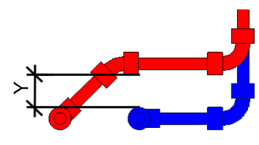
The Angle drop-down list allows you to select an angle dimension for the bypass. If you select Auto, the angle automatically adjusts to the construction situation.
If LINEAR cross over, standard is selected, clear distances and angles are automatically determined for the bypass. The corresponding fields are therefore not active. If you select with single fittings, you can make these settings yourself.
Save on fittings when bypassing
Depending on the spatial situation, additional fittings may be required when bypassing under or over the main pipe to be crossed. When this option is selected, the program reduces the use of fittings and adjusts the connection accordingly. This option is disabled if you have selected LINEAR cross over, standard for bypassing.
| Activated | Deactivated |
|---|---|
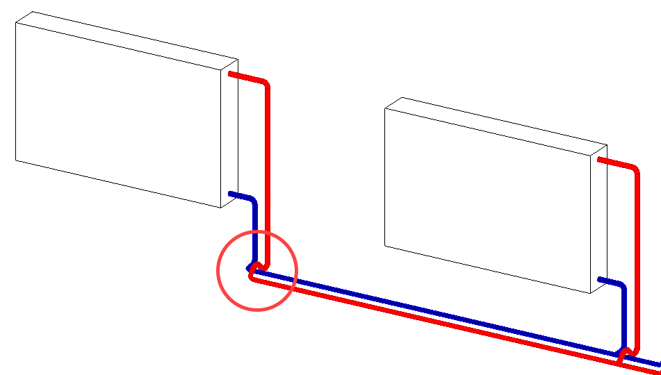
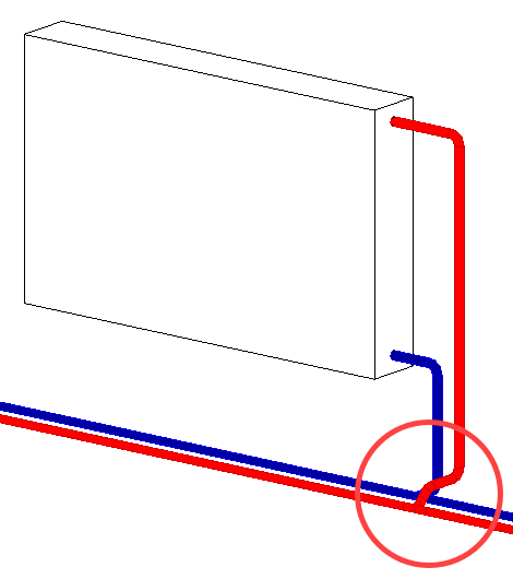 The pipes are initially constructed vertically downwards from the component. The pipe that crosses the main pipe is not led to the height of the main pipe, but a little further up. This allows the pipe to be connected directly horizontally to the main pipe and saves additional fittings when bypassing. The field for the value [X] of the clear distance and the selection for Angle are disabled. | 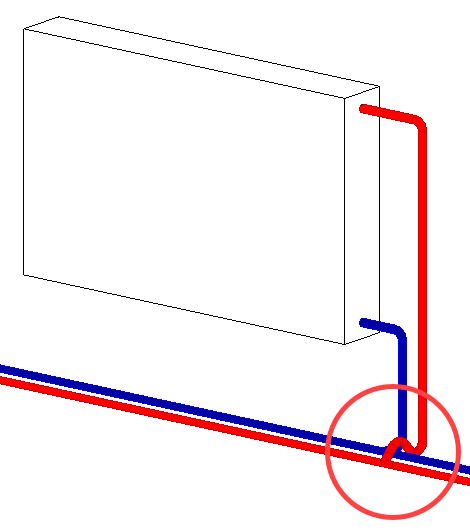 The pipe that crosses the main pipe is first led vertically downwards to the level of the main pipe. Additional fittings are required for the bypass. |
Bypass below
For horizontally running main pipes, you determine whether the bypass should be below the pipe to be crossed, unlike the default setting.
For vertically running main pipes, the bypass is placed in front of or behind the pipe to be crossed.
| Activated | Deactivated |
|---|---|
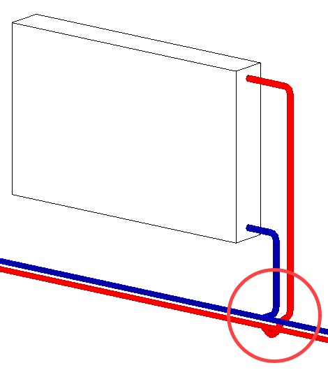 The connection is led under the main pipe to be crossed, if the main pipe is parallel to the component. | 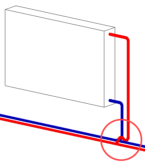 The connection is laid over the main pipe to be crossed. |
Bends on last components
| Activated | Deactivated |
|---|---|
 The last components of a pipe run are connected using bends, thereby creating a closed pipe system. | 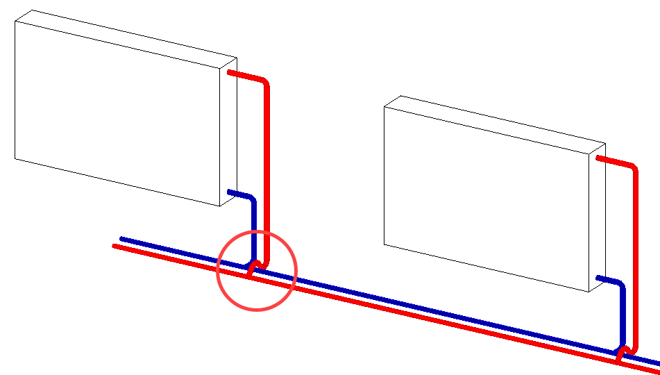 The last components are connected with T-pieces. The pipe remains open. This can be useful if further construction is required at this point. |