Details on the Calculation Dialog for Ventilation
Information about the Duct network calculation dialog.
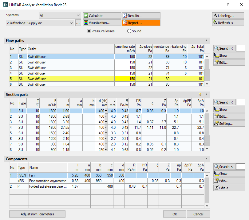
The calculation dialog shows an overview of the detected duct network and contains all functions necessary for calculation.
You are here:
Functions for the calculation
The functions in the upper part of the calculation dialog pertain to the entire duct network.
| Element | Meaning |
|---|---|
| Systems | If the project contains several systems or partial networks you may determine which of the systems or partial network to display in the calculation dialog’s tables. You can use the drop-down list Systems to filter the selection by external or room-side systems. |
| … | This button will open the dialog for technical data of the initial component. Here, you can change the system name shown in the drop-down list. |
 Calculate | Initiate the calculation of the pipe network after having made changes to see current calculation results. If you have activated the Recalculate after editing checkbox in the Settings dialog, the calculation is automatically performed again after each editing of section parts or components. |
 Visualization... | This function displays properties and calculation results of the pipe network in color in the model. |
 Result... | Displays additional information regarding the pipe network and an overview of the calculation results, which also are part of the printouts. |
 Report... | Displays an overview of notes and errors that occurred during calculation. The color of the button helps differentiate between notes and errors: white: No notes or errors. orange: There are notes on the calculation. red: There are errors in the calculation. Note: It is recommended to always carefully read the reports to correct errors in the drawing and ensure a proper calculation. |
 Labeling... | Label components and section parts with calculation results. |
 Refresh < | If components or section parts have already been labeled and calculation results have changed retrospectively, this button will refresh all labels with current data. |
| Adjust nominal diameters | If calculated nominal diameters deviate from those constructed, calculated nominal diameters can be transferred into the model. You can adjust the nominal diameters for the entire network or for partial networks. |
| Pressure losses, Sound | These radio buttons allow you to switch between results of pressure loss calculation and sound level calculation. The table for flow paths displays pressure losses or the results of sound level calculation, respectively. |
Functions of the tables
In sections Flow paths , Section parts and Components, similar functions are presented.
| Element | Description |
|---|---|
 Lock/Unlock section parts | Opens the dialog in which you define or solve the dimensioning of all components of the selected system, the selected flow path or the selected section part. Locked dimensions are shown in bold in columns a, b or d and are not changed during dimensioning. The calculation determines the pressure losses, and the upstream dimensioning determines the dimensions of the duct sections, depending on the set boundary conditions. |
 Maximize list | The tables for flow paths, section parts and components can be maximized to fit the entire calculation dialog. The other tables are hidden. |
 Minimize list | This function minimizes a maximized table. The other tables are displayed again. |
 Search < | This function is available in sections Flow paths , Section parts and Components. After clicking Search < select the element in the model. The respective table then highlights the flow path, the section part or the component. If a certain flow path number, a section part number or a component number needs to be found, enter the number into the text field and click Search <. The respective table then highlights the flow path, the section part or the component. |
 Show | This function is available in sections Flow paths , Section parts and Components. First, select the element from the table and click Show. The flow path, the section part or the component is shown in the model. |
 Edit... | This function is available in sections Flow paths , Section parts and Components. First, select the element in the table and click Edit.... The dialog for editing components or section parts is opened. |
 Configure... | This function is available in section Section parts. Opens the dialog Define section parts. This function allows you to assign certain properties to selected or all section parts simultaneously. |
 edit in drawing < | This function is available in sections Section parts and Components. Select the element in your model after clicking edit in drawing <. The dialog for editing components or section parts is opened. |
Flow paths, section parts, components
The tables contain all flow paths, section parts and components of the calculated duct network. The Flow Paths table shows all flow paths present in the calculated duct network. The Section parts table shows the section parts of the flow path selected under flow paths. The Components table shows all components contained in the selected section part.
Further information can be found in the linked topics.