Details on the Heating and Cooling Calculation Dialog
Information about the dialogs for Heating pipe network and Cooling pipe network.
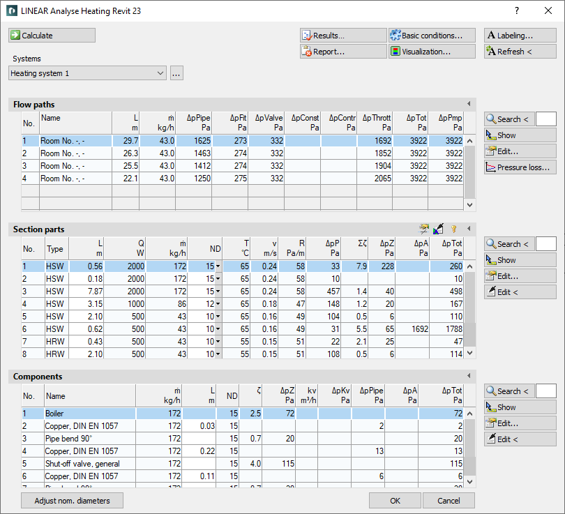
The calculation dialog shows an overview of the detected pipe network and contains all functions necessary for the calculation.
You are here:
Applies to: Heating, Cooling.
Functions for the calculation
The functions in the upper part of the calculation dialog pertain to the entire pipe network.
| Element | Meaning |
|---|---|
 Calculate | Initiate the calculation of the pipe network after having made changes to see current calculation results. |
| Systems | If the project contains several systems or partial networks you may determine which of the systems or partial network to display in the calculation dialog’s tables. |
| … | This button will open the technical data of the initial component. Here, you can change the system name shown in the drop-down list. |
 Result... | Displays additional information regarding the pipe network and an overview of the calculation results, which also are part of the printouts. |
 Report... | Displays an overview of notes and errors that occurred during calculation. The color of the button helps differentiate between notes and errors: white: No notes or errors. orange: There are notes on the calculation. red: There are errors in the calculation. Note: It is recommended to always carefully read the reports to correct errors in the drawing and ensure a proper calculation. |
 Basic conditions... | Opens the dialog Basic conditions, which allows you to change basic calculation-parameters like specifications for hydraulic balancing, upper limits for max. velocities, max. pipe friction pressure gradient as well as settings for the dimensioning of thermostatic valves, regulating valves and differential pressure closed-loop controllers. |
 Visualization... | This function displays properties and calculation results of the pipe network in color in the model. |
 Labeling... | Label components and section parts with calculation results. |
 Refresh < | If components or section parts have already been labeled and calculation results have changed retrospectively, this button will refresh all labels with current data. |
| Adjust nominal diameters | If calculated nominal diameters deviate from those constructed, calculated nominal diameters can be transferred into the model. You can adjust the nominal diameters for the entire network or for partial networks. |
Functions of the tables
In sections Flow paths, Section parts and Components, similar functions are presented.
| Element | Description |
|---|---|
 Maximize list | The tables for flow paths, section parts and components can be maximized to fit the entire calculation dialog. The other tables are hidden. |
 Minimize list | This function minimizes a maximized table. The other tables are displayed again. |
 Search < | This function is available in sections Flow paths, Section parts and Components. After clicking Search < select the element in the model. The respective table then highlights the flow path, the section part or the component. If a certain flow path number, a section part number or a component number needs to be found, enter the number into the text field and click Search <. The respective table then highlights the flow path, the section part or the component. |
 Show | This function is available in sections Flow paths, Section parts and Components. First, select the element from the table and click Show. The flow path, the section part or the component is shown in the model. |
 Edit... | This function is available in sections Flow paths, Section parts and Components. First, select the element from the table and click Edit.... The dialog for editing components or section parts is opened. |
 edit in drawing < | This function is available in sections Section parts and Components. Select the element in your model after clicking edit in drawing <. The dialog for editing components or section parts is opened. |
Table for flow paths
This table shows the calculation data for all flow paths of the selected system. It provides an overview over all ending components of the network. If you select a flow path, the table Section parts displays all corresponding section parts. The most unfavorable flow path is highlighted in a different color. You can also select the most unfavorable flow path by pressing U.
 Apply output data from Family parameters
If radiator families are used that are not from LINEAR but bring their own parameters for capacity and mass flow, these data can be used for the calculation. After clicking , you can choose to either assign capacity output or mass flow rate to their respective LINEAR parameter.
 Pressure loss
Opens the dialog Flow path data in which pressure losses over the course of a flow path are shown in a graph.
| Column | Description |
|---|---|
| No. | Flow path number. |
| Name | Name of the heat- or chill consumer. |
| L | Length of the flow path. Changes for length in the tables section parts and components take effect after the next calculation. |
| m | Mass flow rate of the heat- or chill consumer. The tooltip shows the component number and the power output of the consumer. |
| dpPipe | Pressure loss due to pipe friction. |
| dpFit | Pressure loss due to fittings (e. g. bends, t-pieces, reducing parts, transitions, manifolds). |
| dpValve | Pressure loss due to cv-values of valves (e. g. fixed resistors, shut-off valve). |
| dpConst | Constant pressure losses due to manually entered values (e.g. for radiators, heat exchanger). |
| dpContr | Pressure loss through 3-way control valves. |
| dpThrot | Pressure loss due to throttling valves (e. g. throttle valve, regulating valves). |
| dpTot | Pressure loss for the entire flow path. |
| dpPmp | Total pressure loss in flow path overcome by the pump. The tooltip displays the number of pumps. |
Table for section parts
This table shows the calculation data for all section parts of the selected flow path. If you select a section part, the table Components displays all corresponding components.
 Apply section part data globally
Opens the dialog Define section parts. This function allows you to assign or reset certain properties of selected or all section parts.
 Unfix / fix section parts
This function allows you to fix or unfix the dimensions of all section parts. If values are displayed in bold in theDN column, the dimension of the respective section parts will not be adjusted during the calculation. This is sensible when calculating existing systems. If the dimensions of some section parts have been fixed already, you will be asked whether to fix or unfix all section parts.
 Built-in parts or fittings can be classified as section separators
This function allows you to classify fittings or built-in parts in the pipe network as separating elements for section parts, e.g. in order to assign different pipe material or to create clear separations for the automatic assignment of material.
| Column | Description |
|---|---|
| No. | Number of the section part. |
| Type | HSW: Supply water HRW: Return water SWHC: Supply water Heating/Cooling RWHC: Return water Heating/Cooling |
| L | Length of section part. The length be changed in the table. The new length will be distributed among all pipes of the section parts proportionately to constructed length. All pipes affected by the change in length will be displayed bold in the tables for section parts and components. |
| Q | Heat flow rate of this section part. The tooltip shows the simultaneity and the resulting heat flow rate. |
| m | Mass flow rate in this section part. The tooltip shows the simultaneity and the resulting heat flow rate. |
| DN | Nominal diameter of pipes in this section part. The Nominal can be changed in the table. The value is then fixed and will not be adjusted by the software during calculation. Fixed values are shown in bold. |
| T | Design operating temperature. The tooltip shows the operating temperature, the ambient temperature and the specific heat loss. |
| v | Mean flow velocity in this section part. |
| R | R-value in pipes. |
| dpR | Pressure loss due to pipe friction. |
| Sum zeta | Sum of zeta values in this section part. |
| dpZ | Pressure loss due to zeta value. |
| dpA | Pressure losses of adjustable appliances and valves. |
| dpTot | Sum pressure loss of this section part. |
Table for components
This table shows the calculation data for all Components of the selected section part.
| Column | Description |
|---|---|
| No. | Component number. |
| Name | Name of the component. |
| m | Mass flow rate of this component. |
| L | For pipes: Length. The length be changed in the table. The new length will be used in all section parts containing the respective pipe. All pipes affected by the change in length will be displayed bold in the tables for section parts and components. |
| DN | Dimension. VAR: Dimension varies. |
| Zeta | Zeta value of component. |
| dpZ | Pressure loss of this built-in part. |
| Cv | Flow coefficient. |
| dpKv | Pressure loss due to Cv value. |
| dpPipe | Pressure loss of this pipe. |
| dpA | Pressure loss by appliances. |
| dpTot | Total pressure loss of this component. |