Calculation
Explains the concept of the calculation dialog in Pipe and Air Duct Network Calculations.
General information
Use the button Calculation to start detection of the pipe and duct network along with the automatically following calculation including dimensioning of pipes and ducts.
After calculating, the calculation dialog opens. The calculation dialog provides an overview of the pipe network. All systems, flow paths, section parts, components contained by the pipe or duct network and their calculation results are listed in tables. By clicking Edit... you may further specify settings for flow paths, section parts and components.
You can adjust the configuration in the Settings dialog, the specifications for the pipe or duct material used, the settings for the insulation and the technical data of the components at any time. Even if you make changes in the construction of the pipe or duct network or add or change components, this is not a problem. When detecting and calculating the pipe- or duct network, the calculation dialog always displays current calculation results.
Flow paths
Within the selected system, a flow path is the entire way from the initial component through built-in parts up to the ending component.
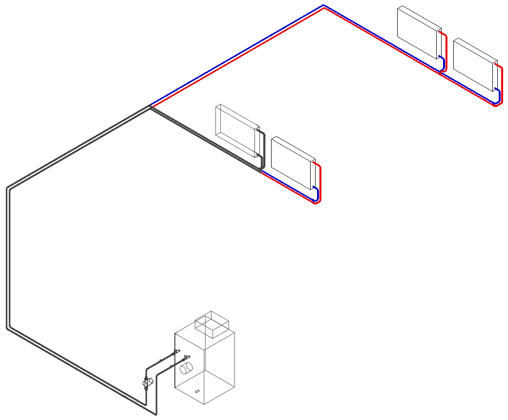
Section parts
Each flow path is divided into section parts. The first section part leads from the initial component up to the next t-piece or built-in part that features a change in nominal diameter or material. All following section parts lead from t-piece or built-in part up to the next t-piece or built-in part. The last section part leads from the last t-piece or built-in part up to the ending component.
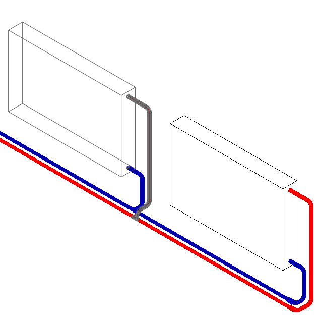
Section parts are divided by the following components:
- Branches
- Transitions
- Components for change of dimension or material
- System-dividing components like pumps, hydraulic separator or heat exchanger.
Depending on the selected discipline, other components can divide a section part:
Heating:
- Pumps
- Manifolds
- Buffer storage
- Hydraulic separator
- Three-way valves
- Heat exchanger
Potable Water:
- Pumps
- Manifolds
Waste Water:
- Lifting station
- Sometimes: bends, if they switch direction from vertical to horizontal and thereby impact pipe type.
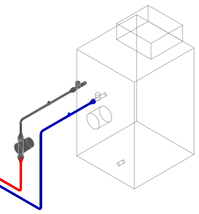
Components
- Initial and ending components
- Pipes or ducts
- Built-in parts
- Fittings like t-pieces, branches, bends
Further functions
Depending on the selected discipline, further functions for the calculation are available in the calculation dialog. You can view summarized calculation results, see notes and error reports regarding the calculation and label the pipe network. The function Visualization allows you to visualize different properties of the network in the model.
If all settings have been made and the pipe- or duct network will not be changed anymore, you can, as a last step, transfer the calculated nominal diameters into the model by using the function Adjust nominal diameters. You can adjust the nominal diameters for the entire network or for partial networks.