Designing Suspended Ceilings
Get information about the possibilities of modeling rooms with suspended ceilings for building detection.
The clear room height is used to determine the interior volume as well as the enveloping surface for the air tightness test. In residential buildings, the clear room height usually extends from the top edge of the finished floor up to the bottom edge of the ceiling. In non-residential buildings, e.g. office buildings, ceilings are usually suspended. Since the intention is usually to hide technical components, they are usually opaque, but not necessarily airtight. In most cases, suspended ceilings are not particularly thermally relevant and can be neglected in the calculation, but they may reduce the net volume of the room.
The result is that different cases with regard to the building registration have to be distinguished.
Highly air-permeable ceiling (e.g. lamellas)
For this type of suspended ceiling, the area between the suspended ceiling and the lower edge of the raw ceiling should be included in the net volume of the MEP spaces.
Modeling in Revit
Mostly airtight ceiling (e.g. sheetrock)
This type of suspended ceiling by its design reduces the net volume of the MEP space.
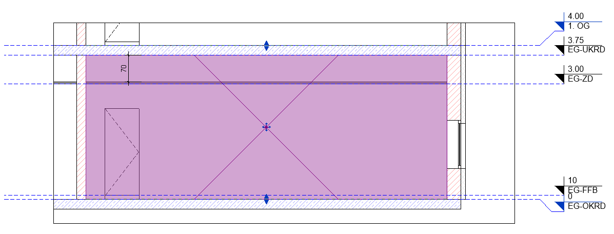
In the case of mostly airtight suspended ceilings, the suspended ceiling shall be defined as room bounding and the suspended ceiling has to be of the type Ceilings. The volume of the suspended area should not be included in the net volume of the MEP space, since there is no air exchange between the space above the suspended ceiling and the actual room.
If the detection encounters the room bounding suspended ceiling when the MEP space is placed, the program tries to continue the detection up to another 250 cm of distance to find the raw ceiling. The raw ceiling is detected with a thickness of up to 100 cm, so that a layered component with a total thickness of up to 350 cm can be detected. Since the distance between the lower edge of the raw ceiling and the suspended ceiling in the picture below is 70 cm, the raw ceiling is found and identified as a layered component together with the suspended ceiling, and after detecting it is also listed as such in the master tables. The correction of gross area as well as storey height is carried out automatically during this step.
If the distance between the suspended ceiling and the upper edge of the raw ceiling is more than 350 cm, the detection does not find any neighboring rooms or components and the area is detected as outside air. In such cases, an unoccupied MEP space with appropriate temperature assignment should be placed between the suspended ceiling and the lower edge of the unfinished ceiling so that components adjacent to this area are not detected as being adjacent to outside air.
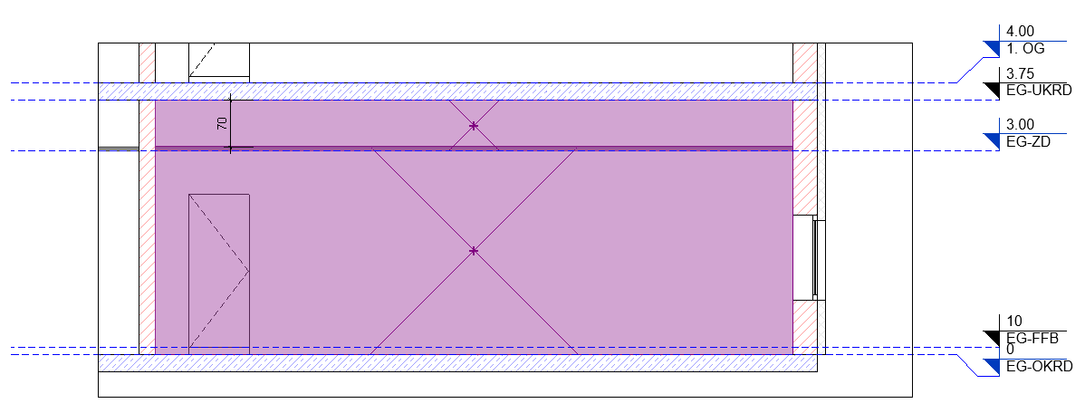
Mostly airtight, but only partially suspended ceiling
For mostly airtight suspended ceilings that extend over only part of the room, proceed in the same way as for largely airtight suspended ceilings that extend over the entire surface of the ceiling. The suspended ceiling must be defined as room bounding. If the distance to the lower edge of the raw ceiling is less than 250 cm and the raw ceiling above is max. 100 cm thick, no measures are necessary. If the distance is greater, for the reasons stated above, place an unoccupied MEP space with appropriate temperature assignment.