Details on Room Data
Information on the Room data section when calculating the cooling load by the abbreviated method.
You are here:
General room data
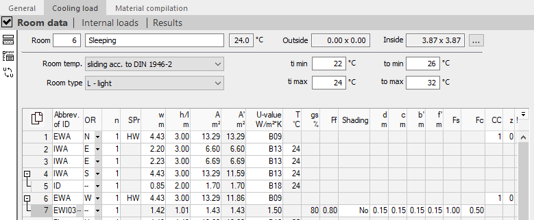
The upper part of this view shows the room number, the room name, the set room temperature for cooling and the dimensions of the room (the latter not in cases where only the area was given). The room number and room name can be edited directly. If a constant temperature has been set at project level or in the room (under Room temperature), this can also be adjusted here directly. If a continuously changing temperature has been set at project level, the given temperature interval ti min – ti max is taken into account in the cooling load calculation. The room dimensions can be adjusted by clicking on  .
.
Temperature data
Room temperature: Determines whether the room temperature remains constant over the course of the day or is changed continuously as per DIN 1946-2. If you select a constant room temperature, the room temperature for the cooling case from the general room data is used for the room cooling load calculation. If you select the continuously changing room temperature according to DIN 1946-2, the room temperature for the cooling case dependent on the exterior air temperature according to the DIN 1946 Part 2 comfort criteria is used for the room cooling load calculation.
Room type: Energy storage effect of the room.
ti min, ta min, ti max, ta max: Gives the minimum and maximum interior and exterior air temperatures over the course of the day for calculating the continuously changing room air temperature according to DIN 1946.
Components/Component data
This table contains an overview of the components and component data for the individual rooms, such as walls, windows or doors.
By clicking  you have the possibility to copy the contents of the table with or without column heading and paste it into Excel.
If you have selected individual rows or cells, you can copy the selected data with the key combinations Ctrl+C (with column heading) or Ctrl+Shift+C (without column heading) and paste it into Excel, for example.
Code no.:
Abbreviation for the type of component. The software differentiates between predefined components from the master tables and component types. The predefined components are defined in more detail via the numbering and can already contain U-values and dimensions. Predefined components can be adjusted in the master tables.
You can enter an abbreviation for the type of component or a component directly in the column. Alternatively, you can select a component or a component group from the table by pressing F8 or by clicking  . The following component types are available for selection:
| Component code | Component |
|---|---|
| EWA | Exterior walls (also adjoining to ground) |
| EWI | Exterior windows |
| ED | Exterior doors |
| RF | Roof |
| RW | Roof window |
| CL | Ceiling |
| FL | Floor |
| IWA | Interior walls |
| IWI | Interior windows |
| ID | Interior doors |
| DAR | Pure deduction area this area is considered to be an opening without any thermal calculation. |
HR
Cardinal point in which the component or area is located. It is used to label the gross area and to calculate the solar cooling load of walls, windows and roofs. Deduction areas are not given a cardinal point. Instead, these areas are marked with -- as deduction area (a "-" is sufficient as input). The specification H (horizontal) can be used for ceilings, floors, roofs and roof windows.
n
Number of equal areas The number of equal areas is a multiplier. The input is limited to whole positive numbers. If areas are only to be considered partially, the values in the Width and Height columns can be adjusted accordingly.
OF
Specifies the surface properties of the exterior component. Click in the line and select to open the Exterior component surface, where you can select the component’s surface properties.
b, h/l, A m², A' m²
In these four columns you define the width, height, length or area of the heat-transferring outer area. If the width, height or length is entered, the area is calculated from the data. If the area is entered, the entries for width, height or length are deleted. In column A’ m² the area minus all deduction areas is displayed.
In these fields it is possible to enter dimensions as a term. Enter the term e.g. with 2.25+1.35 and press Enter. The result is calculated and entered. For areas that, for example, like gable walls, are only partially included in the calculation, the dimensions can be entered with a corresponding factor (e.g. 0.5 * width/height for triangular areas).
Double-clicking F8 or the button takes you to the Width field in the Room dimensioning dialog and, for ceilings etc., also to the Height/Length field. Here, you enter the overall dimensions and wall thicknesses. The relevant measurement is calculated from this data.
U-value
The physical U-values are calculated according to DIN EN ISO 6946. Enter a U-value directly as a number or press F8 or click on to select a previously calculated U-value from the list. In the master tables you can create new components, have their U-values calculated or enter and save them directly.
t
Gives the temperature of the adjoining rooms, if this is relevant for the room’s cooling load calculation. Press F8 or click on to open the Temperatures dialog, where you can select a suitable temperature from a table of room types.
gs
Gives the energy transmittance of a window’s glazing in percent. Press F8 or click on to open the Glass/TWD energy transmittance dialog, where you find a table with the variable energy transmittances for different grades of glass. You can only change the energy transmittance of a window, if you have not selected a standard window.
Ff
Defines the glazed area of the window. You can only change the glazed area of a window if you have not selected a standard window.
Bs
Defines the shading option. If the Global option has been activated in the general cooling load data, the Shading field in the windows in the room view is deactivated. If, in the room view, you have already entered different data for individual windows for the value of Shading, this data is saved if you activate the Global option in the general cooling load data. With exterior windows, the global settings are then shown and used for the calculation. If the option is deactivated, the original data is again visible in the room view. Depending on which type of shading is entered in the Bs field, the values for the following fields d, c, b‘, f‘ and Fs are considered as different types.
| Shading | Description |
|---|---|
| K (No shading) | No shading. The fields d, c, b', f' and Fs are not considered. |
| F (Fixed value for the shading) | Uniform shading over the course of the day without moving shadows. Only the value Fs is considered; the values d, c, b' and f' are not used for projections at the windows. |
| B (Calculated value for shading) | The shading change over the course of the day is calculated via the projections around the window (dimensionsd, c, b' and f'). The value in the field Fs is not used. |
d, c, b', f'
Defines the value for the side projection dimension d, the top projection dimension c, the distance of the frame from the side projection b' and the distance of the frame from the top projection f'. In any cell of these columns, press F8 or click on in order to open the Window dimensions dialog, where you can find a graphic overview of the window dimensions and enter their values.
Fs
If under shade type Shading you have selected the setting F= 'Fixed value for shading (Fs)', the factor Fs is also required for the calculation. You can enter a value between 0 and 1. The smaller Fs, the less solar radiation penetrates to the interior of the building through the window. If you enter Fs = 1, the heat flow reaching the inside of the building through the window is not reduced. If you enter Fs < 1, the heat flow is reduced by a fixed value constantly over the course of the day. This is the case, for example, with dynamic façades, where the shutters are controlled automatically by light sensors. If you enter Fs = 0, only the diffuse component of the light is considered (VDI 2078). This occurs above all in inner cities where a building’s windows may never be directly lit by the sun.
Fc
An additional reduction factor Fc (or b) can be entered for exterior or interior solar protection devices. Enter a value between 0 and 1 or select a suggestion from the table. Fc = 1 means that no solar protection device is present and the heat flow through the window into the interior of the building is not reduced. A Fc of 0 means that only exterior solar protection is present. A Fc between 0 and 1 means that an interior solar protection or a combination between interior and exterior solar protection is present. Pressing F8 or clicking on opens Shading device, Fc value/ b value, where you can select a Fc or b value.
CC
Defines the construction class of walls and roofs. Pressing F8 or clicking on opens the Construction classes dialog, where you can select a construction class.
z
Defines the time correction of walls and roofs.